Get Started with Graphics3DControl
This tutorial demonstrates how to create a 3D model and display it a Graphics3DControl control. The example uses the API exposed by the control to define meshes, vertices, and materials.
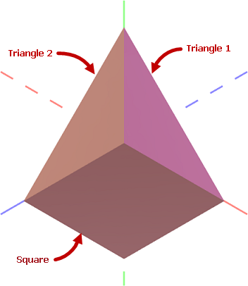
You can display multiple 3D models in a Graphics3DControl simultaneously. This tutorial creates one 3D model. It consists of a square and two triangles positioned at right angles to each other. Each figure is painted using its own material.
Create a Graphics3DControl
Create a Graphics3DControl control in XAML using the following code:
xmlns:mx3d="https://schemas.eremexcontrols.net/avalonia/controls3d"

<mx3d:Graphics3DControl Name="g3DControl" ShowAxes="True">
    <mx3d:Graphics3DControl.Camera>
        <mx3d:IsometricCamera/>
    </mx3d:Graphics3DControl.Camera>
</mx3d:Graphics3DControl>
This code displays axes and enables the isometric camera for the Graphics3DControl control. You can also enable a perspective camera. For this purpose, set the Graphics3DControl.Camera property to a PerspectiveCamera object.
Define a 3D Model
The GeometryModel3D class encapsulates a 3D model for a Graphics3DControl. To add 3D models to the control, add one or multiple GeometryModel3D objects to the Graphics3DControl.Models collection.
using Eremex.AvaloniaUI.Controls3D;

GeometryModel3D model = new GeometryModel3D();
g3DControl.Models.Add(model);
A 3D model consists of one or more meshes. A mesh is a part of the model painted using a specific material.
The square and triangle figures in the 3D model are painted with their own materials. Thus three meshes need to be created.
Add Meshes
Use the GeometryModel3D.Meshes collection to add meshes. Each mesh is encapsulated by a MeshGeometry3D object.
using DynamicData;

MeshGeometry3D meshTriangle1 = new MeshGeometry3D();
MeshGeometry3D meshTriangle2 = new MeshGeometry3D();
MeshGeometry3D meshSquare = new MeshGeometry3D();
//...
model.Meshes.AddRange(new[] { meshTriangle1, meshTriangle2, meshSquare });
Graphics3DControl supports three mesh types:
- Mesh defined by a collection of triangles (default, or when
MeshGeometry3D.FillTypeis set toMeshFillType.Triangles) - Mesh defined by a collection of lines (when
MeshGeometry3D.FillTypeis set toMeshFillType.Lines) - Mesh defined by a collection of points (when
MeshGeometry3D.FillTypeis set toMeshFillType.Points)
In the current example, meshes are created from triangles. For this mesh type, you need to specify the following properties:
MeshGeometry3D.Vertices— An array of all vertices (Vertex3Dobjects) that make up the mesh. AVertex3Dobject exposes the following main properties:Vertex3D.Position— AVector3object that specifies the coordinates of a vertex.Vertex3D.Normal— AVector3object that specifies the vertex normal. Vertex normals are directional vectors used to calculate light reflection for the vertices and triangle.Vertex3D.TextureCoord— AVector2object that specifies the coordinates of a texture for the current vertex.
MeshGeometry3D.Indices— An array of indices of vertices in theVerticesarray that define individual mesh triangles. This array contains groups of three indices each. The first three indices in the array refer to the vertices of the first mesh triangle. The next three indices refer to the vertices of the second mesh triangle, and so on. The order of the indices for each triangle is important because it determines the surface normal. The surface normal, in turn, identifies the front and back sides of the triangle, which is essential for operations like back-face and front-face culling.
Define Meshes for the Triangle 1 and Triangle 2 Figures
Meshes for the Triangle 1 and Triangle 2 figures are easy to define as these figures already represent triangles.
First, let's identify all vertices in the created 3D model and their (x, y, z) coordinates.
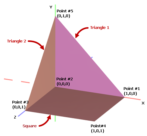
In code, define the coordinates of all vertices using Vector3 objects:
Vector3 pt1 = new(1, 0, 0);
Vector3 pt2 = new(0, 0, 0);
Vector3 pt3 = new(0, 0, 1);
Vector3 pt4 = new(1, 0, 1);
Vector3 pt5 = new(0, 1, 0);
Initialize the vertices and indices for the Triangle 1 figure:
Vertex3D[] meshTriangle1Vertices = new Vertex3D[]
{
    new Vertex3D() { Position = pt2,  Normal = new Vector3(0, 0, 1) },
    new Vertex3D() { Position = pt5,  Normal = new Vector3(0, 0, 1) },
    new Vertex3D() { Position = pt1,  Normal = new Vector3(0, 0, 1) },
};

// Define a mesh triangle.
uint[] meshTriangle1Indices = new uint[] { 0, 1, 2 };

meshTriangle1.Vertices = meshTriangle1Vertices;
meshTriangle1.Indices = meshTriangle1Indices;
Here, the indices 0, 1 and 2 refer to the first, second and third vertices in the Vertices array.
Similarly, initialize the vertices and indices for the Triangle 2 figure:
Vertex3D[] meshTriangle2Vertices = new Vertex3D[]
{
    new Vertex3D() { Position = pt2,  Normal = new Vector3(1, 0, 0) },
    new Vertex3D() { Position = pt5,  Normal = new Vector3(1, 0, 0) },
    new Vertex3D() { Position = pt3,  Normal = new Vector3(1, 0, 0) }
};

// Define a mesh triangle.
uint[] meshTriangle2Indices = new uint[] { 0, 1, 2 };

meshTriangle2.Vertices = meshTriangle2Vertices;
meshTriangle2.Indices = meshTriangle2Indices;
Define Meshes for the Square Figure
The Square figure can be divided into two mesh triangles. For example:
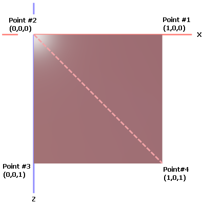
The Vertices array for the Square mesh should contain four points. The Indices array should contain six indices that identify two mesh triangles.
Vertex3D[] meshSquareVertices = new Vertex3D[]
{
    new Vertex3D() { Position = pt1,  Normal = new Vector3(0, 1, 0) },
    new Vertex3D() { Position = pt2,  Normal = new Vector3(0, 1, 0) },
    new Vertex3D() { Position = pt3,  Normal = new Vector3(0, 1, 0) },
    new Vertex3D() { Position = pt4,  Normal = new Vector3(0, 1, 0) }
};

// Define two mesh triangles.
// The first mesh triangle is formed by points pt1, pt2 and pt4.
// The second mesh triangle is formed by points pt2, pt3 and pt4.
uint[] meshSquareIndices = new uint[] { 0, 1, 3, 1, 2, 3 };

meshSquare.Vertices = meshSquareVertices;
meshSquare.Indices = meshSquareIndices;
Specify Materials
Graphics3DControl control supports the following materials, derived from the Eremex.AvaloniaUI.Controls3D.Material abstract class:
SimplePbrMaterial— A material that describes the visual properties of a surface as numeric values:Albedo— Base colorAlpha— TransparencyEmission— Intensity of light emitted from the surfaceAmbientOcclusion— Level of the shadowing caused by objects blocking the ambient lightRoughness— Smoothness of the surfaceMetallic— Reflectivity of the surface.
TexturedPbrMaterial— A textured material in PBR format. This material allows you to specify the visual properties (Albedo,Alpha,Emission,AmbientOcclusion,Roughness,MetallicandNormal) of a surface as bitmaps.
You need to assign unique keys (string values) to the materials using the Material.Key property.
Then you can associate a material to a mesh from the MeshGeometry3D.MaterialKey property.
The following code, adds three materials (SimplePbrMaterial objects) with specific base colors (Albedo). Created meshes are associated with the materials using the MaterialKey property.
using DynamicData;

g3DControl.Materials.AddRange(
    new[] {
        new SimplePbrMaterial(Color.FromUInt32(0xFF822c2e), "BrownColor"),
        new SimplePbrMaterial(Color.FromUInt32(0xffeb523f), "TomatoColor"),
        new SimplePbrMaterial(Color.FromUInt32(0xFFea3699), "VioletColor")
    }
);

//...

meshTriangle1.MaterialKey = "VioletColor";
meshTriangle2.MaterialKey = "TomatoColor";
meshSquare.MaterialKey = "BrownColor";
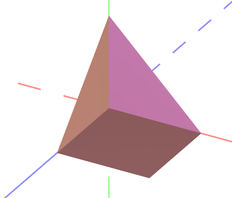
Run the Application
Now you can run the application. Use the mouse and keyboard to pan, zoom and rotate the created 3D model.
Complete Code
<mx:MxWindow xmlns="https://github.com/avaloniaui"
        xmlns:x="http://schemas.microsoft.com/winfx/2006/xaml"
        xmlns:vm="using:G3DControl_Get_Started.ViewModels"
        xmlns:d="http://schemas.microsoft.com/expression/blend/2008"
        xmlns:mc="http://schemas.openxmlformats.org/markup-compatibility/2006"
        xmlns:mx="https://schemas.eremexcontrols.net/avalonia"
        xmlns:mx3d="https://schemas.eremexcontrols.net/avalonia/controls3d"
        xmlns:mxe="https://schemas.eremexcontrols.net/avalonia/editors"

        mc:Ignorable="d" d:DesignWidth="800" d:DesignHeight="450"
        x:Class="G3DControl_Get_Started.Views.MainWindow"
        x:DataType="vm:MainWindowViewModel"
        Icon="/Assets/EMXControls.ico"
        Title="G3DControl_Get_Started">

    <Design.DataContext>
        <!-- This only sets the DataContext for the previewer in an IDE -->
        <vm:MainWindowViewModel/>
    </Design.DataContext>

    <mx3d:Graphics3DControl Name="g3DControl" ShowAxes="True">
        <mx3d:Graphics3DControl.Camera>
            <mx3d:IsometricCamera/>
        </mx3d:Graphics3DControl.Camera>
    </mx3d:Graphics3DControl>
</mx:MxWindow>
using Avalonia.Controls;
using Avalonia.Media;
using DynamicData;
using Eremex.AvaloniaUI.Controls.Common;
using Eremex.AvaloniaUI.Controls3D;
using System;
using System.Numerics;

namespace G3DControl_Get_Started.Views;

public partial class MainWindow : MxWindow
{
    public MainWindow()
    {
        InitializeComponent();

        InitG3DControlMaterials();
        InitG3DControlMeshes();
    }

    private void InitG3DControlMaterials()
    {
        g3DControl.Materials.AddRange(
            new[] {
                new SimplePbrMaterial(Color.FromUInt32(0xFF822c2e), "BrownColor"),
                new SimplePbrMaterial(Color.FromUInt32(0xffeb523f), "TomatoColor"),
                new SimplePbrMaterial(Color.FromUInt32(0xFFea3699), "VioletColor")
            }
        );
    }

    private void InitG3DControlMeshes()
    {

        GeometryModel3D model = new GeometryModel3D();
        g3DControl.Models.Add(model);

        Vector3 pt1 = new(1, 0, 0);
        Vector3 pt2 = new(0, 0, 0);
        Vector3 pt3 = new(0, 0, 1);
        Vector3 pt4 = new(1, 0, 1);
        Vector3 pt5 = new(0, 1, 0);

        // Triangle 1
        MeshGeometry3D meshTriangle1 = new MeshGeometry3D();
        // Setting the FillType property to 'Triangles' is not required
        // as 'Triangles' is the default value of the FillType property.
        //meshTriangle1.FillType = MeshFillType.Triangles;
        Vertex3D[] meshTriangle1Vertices = new Vertex3D[]
        {
            new Vertex3D() { Position = pt2,  Normal = new Vector3(0, 0, 1) },
            new Vertex3D() { Position = pt5,  Normal = new Vector3(0, 0, 1) },
            new Vertex3D() { Position = pt1,  Normal = new Vector3(0, 0, 1) },
        };
        // Define a mesh triangle.
        uint[] meshTriangle1Indices = new uint[] { 0, 2, 1 };
        meshTriangle1.Vertices = meshTriangle1Vertices;
        meshTriangle1.Indices = meshTriangle1Indices;
        meshTriangle1.MaterialKey = "VioletColor";

        // Triangle 2
        MeshGeometry3D meshTriangle2 = new MeshGeometry3D();
        Vertex3D[] meshTriangle2Vertices = new Vertex3D[]
        {
            new Vertex3D() { Position = pt2,  Normal = new Vector3(1, 0, 0) },
            new Vertex3D() { Position = pt5,  Normal = new Vector3(1, 0, 0) },
            new Vertex3D() { Position = pt3,  Normal = new Vector3(1, 0, 0) }
        };
        // Define a mesh triangle.
        uint[] meshTriangle2Indices = new uint[] { 0, 2, 1 };
        meshTriangle2.Vertices = meshTriangle2Vertices;
        meshTriangle2.Indices = meshTriangle2Indices;
        meshTriangle2.MaterialKey = "TomatoColor";

        // Square
        MeshGeometry3D meshSquare = new MeshGeometry3D();
        Vertex3D[] meshSquareVertices = new Vertex3D[]
        {
            new Vertex3D() { Position = pt1,  Normal = new Vector3(0, 1, 0) },
            new Vertex3D() { Position = pt2,  Normal = new Vector3(0, 1, 0) },
            new Vertex3D() { Position = pt3,  Normal = new Vector3(0, 1, 0) },
            new Vertex3D() { Position = pt4,  Normal = new Vector3(0, 1, 0) }
        };
        // Define two mesh triangles.
        // The first mesh triangle is formed by points pt1, pt2 and pt4.
        // The second mesh triangle is formed by points pt2, pt3 and pt4.
        uint[] meshSquareIndices = new uint[] { 0, 1, 3, 1, 2, 3 };
        meshSquare.Vertices = meshSquareVertices;
        meshSquare.Indices = meshSquareIndices;
        meshSquare.MaterialKey = "BrownColor";

        model.Meshes.AddRange(new[] { meshTriangle1, meshTriangle2, meshSquare });
    }
}