Graphics3DControl Overview
The Graphics3DControl control allows you to embed 3D models in your Avalonia application. The control supports the rotate, pan and zoom operations using the mouse and keyboard, allowing a user to interact with the models at runtime.
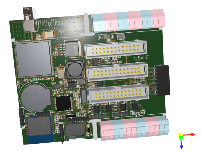
Any 3D model is composed of meshes painted using specified materials. The Graphics3DControl provides an API to define meshes, materials, camera and light settings. You can also utilize third-party libraries to load models in OBJ and STL formats to the Graphics3DControl control.
Main Features
- API to specify 3D models
- Displaying multiple 3D models simultaneously
- Perspective and isometric cameras
- Supported meshes types: triangular, lines and points
- Simple and textured materials
- 3D model transformations
- Front- and back-culling
- Support for the MVVM design pattern to define 3D models
- Displaying axes and grids
User Interactions
- Rotate, pan, and zoom the models using the mouse and keyboard
- Hints
- Element highlight and selection
See User Interactions with 3D Models
Get Started
- Get Started with Graphics3DControl — Demonstrates how to create a 3D model from scratch.
Demos
Check out the Eremex Avalonia Controls Demo application which contains examples demonstrating various features of the Graphics3DControl:
- Loading Wavefront (Obj) and Stl models from external files using third-party libraries, and creating 3D models from the loaded data.
- Creating 3D models from scratch.
- Showcasing the supported mesh types: triangular, lines and points.
- Using the MVVM design pattern to define 3D models, and more.
Coordinate System, Axes and Grids
The Graphics3DControl supports right-handed (default) and left-handed coordinate systems. You can use the Graphics3DControl.CoordinateSystem property to enable the required option.
<mx3d:Graphics3DControl Name="g3DControl" ShowAxes="True" CoordinateSystem="LeftHanded" ...>
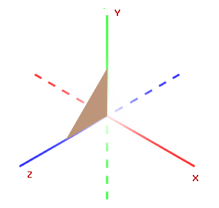
Right-Handed Coordinate System
The positive X, Y and Z axes point right, up and toward the viewer, respectively.
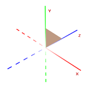
Left-Handed Coordinate System
The positive X, Y and Z axes point right, up and away from the viewer, respectively.
Axes
Enable the Graphics3DControl.ShowAxes property to display the X, Y and Z axes in the control.
<mx3d:Graphics3DControl Name="g3DControl" ShowAxes="True"/>
Related Options
Graphics3DControl.AxisThicknessproperty — Specifies the thickness of the axes.
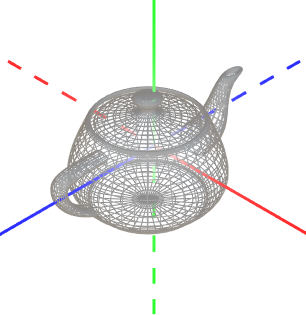
Gizmo
Graphics3DControl can display a gizmo. It is a widget that visually indicates the current orientation of the axes.
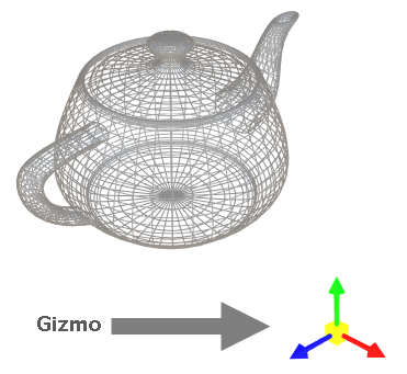
To enable the Gizmo, initialize the Graphics3DControl.Gizmo property with an instance of the Eremex.AvaloniaUI.Controls3D.Gizmo class.
<mx3d:Graphics3DControl Name="g3DControl" >
        <!-- ... -->
    <mx3d:Graphics3DControl.Gizmo>
        <mx3d:Gizmo Name="gizmo" />
    </mx3d:Graphics3DControl.Gizmo>
</mx3d:Graphics3DControl>
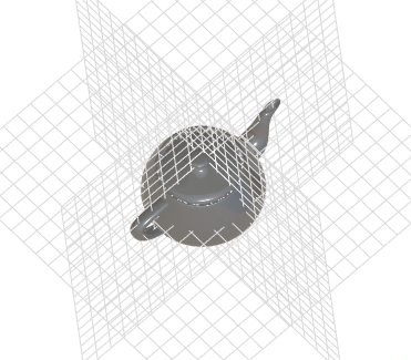
Grids
The Graphics3DControl.ShowGrid property allows you to display grids on the XY, XZ, and YZ planes.
<mx3d:Graphics3DControl Name="g3DControl" ShowGrid="True"/>
Related Options
Graphics3DControl.GridThicknessproperty — Specifies the thickness of grid lines.
Models
To define 3D models for a Graphics3DControl, use the Graphics3DControl's API to create objects that represent models, meshes, vertices, materials, cameras, etc.
Define 3D Models
The GeometryModel3D class encapsulates a single 3D Model in the Graphics3DControl.
Use one of the following properties to add 3D models to the control:
Graphics3DControl.Models— A collection ofGeometryModel3Dobjects.Graphics3DControl.ModelsSource— A source of business objects used to create 3D models (GeometryModel3Dobjects) according to the MVVM design pattern.
xmlns:mx3d="https://schemas.eremexcontrols.net/avalonia/controls3d"

<mx3d:Graphics3DControl Name="g3DControl" ShowAxes="True"/>
using Eremex.AvaloniaUI.Controls3D;

GeometryModel3D model = new GeometryModel3D();
g3DControl.Models.Add(model);
Meshes
A 3D model represents a collection of meshes rendered using specific materials. Meshes define the shape and structure of a 3D object.
The MeshGeometry3D class represents a mesh in the Graphics3DControl. The following properties allow you to specify meshes for the model:
GeometryModel3D.Meshes— A collection ofMeshGeometry3Dobjects.GeometryModel3D.MeshesSource— A source of business objects used to create meshes (MeshGeometry3Dobjects) according to the MVVM design pattern.
The control supports three mesh types, which you can choose with the MeshGeometry3D.FillType property.
MeshFillType.Triangles(default) — A triangle mesh. Consists of triangular faces (flat areas enclosed by three edges).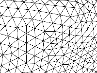
MeshFillType.Lines— Line mesh. Vertices are connected with lines to form a wireframe.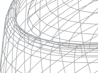
MeshFillType.Points— Point mesh (point cloud). Consists of vertices, which are not connected with lines.
using DynamicData;

MeshGeometry3D meshTriangle1 = new MeshGeometry3D();
MeshGeometry3D meshSquare = new MeshGeometry3D();
MeshGeometry3D meshPoints = new MeshGeometry3D() { FillType = MeshFillType.Points };
//Define the meshes
//...
model.Meshes.AddRange(new[] { meshTriangle1, meshSquare, meshPoints });
When creating a mesh, use the following properties to define vertices and faces/lines:
MeshGeometry3D.Verticesarray — Specifies an array of all vertices that compose the mesh.MeshGeometry3D.Indicesarray — Defines triangular faces (for a triangle mesh), or lines (for a line mesh).
Vertices
A vertex is a point in 3D space defined by its coordinates (x, y, z).
The Vertex3D type encapsulates a single vertex in the Graphics3DControl. Use the MeshGeometry3D.Vertices array to add vertices to a mesh.
The Vertex3D type exposes the following main properties that you need to initialize.
Vertex3D.Position— AVector3value that specifies the (x, y, z) coordinates of the vertex.Vertex3D.Normal— AVector3value that specifies a vertex normal. A vertex normal is a vector that is perpendicular to the surface of a 3D model at that vertex. In 3D graphics, vertex normals are used to calculate lighting and shading for the mesh. The normals of neighboring triangles must be aligned to ensure smooth shading (edges).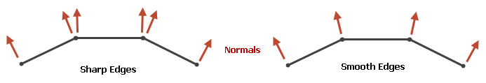
Vertex3D.TextureCoord— AVector2value that specifies the (x, y) coordinates of the point in the textured material that is mapped to the current vertex.
Define a Triangle Mesh
To create a triangle mesh you need to divide a shape into triangles. Vertices specify the corners of the triangles. The MeshGeometry3D.FillType property needs to be set to its default value (MeshFillType.Triangles).
Consider an example in which a mesh has a quadrilateral shape. It can be triangulated by adding a single diagonal.
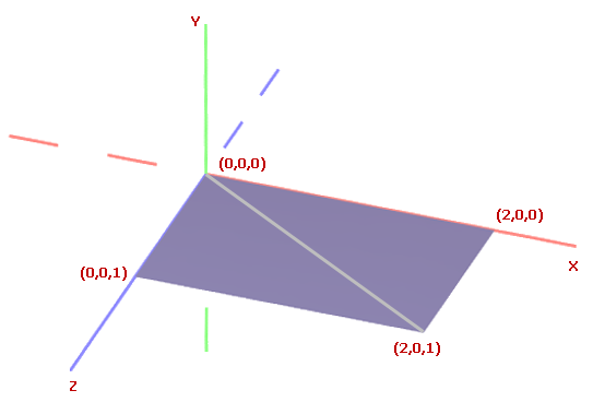
First, add all vertices to the MeshGeometry3D.Vertices array.
<mx3d:Graphics3DControl Name="g3DControl" ShowAxes="True"/>
using DynamicData;

GeometryModel3D model = new GeometryModel3D();
g3DControl.Models.Add(model);

Vector3 pt1 = new(2f, 0, 0);
Vector3 pt2 = new(0, 0, 0);
Vector3 pt3 = new(0, 0, 1);
Vector3 pt4 = new(2f, 0, 1);

MeshGeometry3D meshSquare = new MeshGeometry3D();
meshSquare.FillType = MeshFillType.Triangles;
Vertex3D[] meshSquareVertices = new Vertex3D[]
{
    new Vertex3D() { Position = pt1,  Normal = new Vector3(0, 1, 0) },
    new Vertex3D() { Position = pt2,  Normal = new Vector3(0, 1, 0) },
    new Vertex3D() { Position = pt3,  Normal = new Vector3(0, 1, 0) },
    new Vertex3D() { Position = pt4,  Normal = new Vector3(0, 1, 0) }
};
meshSquare.Vertices = meshSquareVertices;
//...
model.Meshes.AddRange(new[] { meshSquare });
Then use the MeshGeometry3D.Indices property to form triangle faces.
For a triangle mesh, the MeshGeometry3D.Indices property is an array of indices of vertices in the MeshGeometry3D.Vertices array that define individual mesh triangles. This array contains groups of three indices each. The first three indices in the array refer to the vertices of the first mesh triangle. The next three indices refer to the vertices of the second mesh triangle, and so on.
The order of the indices for each triangle is important because it determines the surface normal. The surface normal, in turn, identifies the front and back sides of the triangle, which is essential for operations like back-face and front-face culling.
For the quad mesh above, the MeshGeometry3D.Indices array should contain six indices. The first three indices refer to the vertices of the first triangle. The second three indices refer to the vertices of the second triangle.
uint[] meshSquareIndices = new uint[] { 0, 1, 3, 1, 2, 3 };
meshSquare.Indices = meshSquareIndices;
Define a Line Mesh
In a line mesh, vertices are connected with lines. To define a line mesh, create a MeshGeometry3D object and set its MeshGeometry3D.FillType property to MeshFillType.Lines. Then use the MeshGeometry3D.Vertices property to specify all vertices, and the MeshGeometry3D.Indices property to connect the vertices with lines.
Consider the following 3D model composed of lines connecting six points.
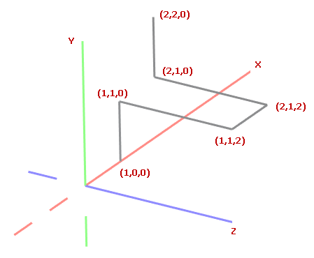
First, add all vertices to the MeshGeometry3D.Vertices array.
<mx3d:Graphics3DControl Name="g3DControl" ShowAxes="True"/>
GeometryModel3D model = new GeometryModel3D();
g3DControl.Models.Add(model);

Vector3 p0 = new(1, 0, 0);
Vector3 p1 = new(1, 1, 0);
Vector3 p2 = new(1, 1, 2);
Vector3 p3 = new(2, 1, 2);
Vector3 p4 = new(2, 1, 0);
Vector3 p5 = new(2, 2, 0);

MeshGeometry3D meshLines = new MeshGeometry3D();
meshLines.PrimitiveSize = 3;
meshLines.FillType = MeshFillType.Lines;
Vertex3D[] meshLinesVertices = new Vertex3D[]
{
    new Vertex3D() { Position = p0,  Normal = new Vector3(0, 1, 0) },
    new Vertex3D() { Position = p1,  Normal = new Vector3(0, 1, 0) },
    new Vertex3D() { Position = p2,  Normal = new Vector3(0, 1, 0) },
    new Vertex3D() { Position = p3,  Normal = new Vector3(0, 1, 0) },
    new Vertex3D() { Position = p4,  Normal = new Vector3(0, 1, 0) },
    new Vertex3D() { Position = p5,  Normal = new Vector3(0, 1, 0) }
};
meshLines.Vertices = meshLinesVertices;
//...
model.Meshes.Add(meshLines);
Use the MeshGeometry3D.Indices property to connect the vertices with lines. For a line mesh, the MeshGeometry3D.Indices property is an array of indices of vertices in the MeshGeometry3D.Vertices array that define individual lines.
This array contains pairs of indices. The first two indices in the array refer to the vertices of the first line. The next two indices refer to the vertices of the second line, and so on.
For the example above, the MeshGeometry3D.Indices array should contain 10 indices. The first pair of indices refers to the points that define the first line. The second pair of indices refers to the vertices of the second line, and so on.
uint[] meshLinesIndices = new uint[] { 0, 1, 1, 2, 2, 3, 3, 4, 4, 5 };
meshLines.Indices = meshLinesIndices;
Thickness of Lines
In a line mesh, use the PrimitiveSize property to change the thickness of lines.
Define a Point Mesh
In a point mesh, vertices are rendered as individual points.
To define a point mesh, create a MeshGeometry3D object and set its MeshGeometry3D.FillType property to MeshFillType.Points. Then use the MeshGeometry3D.Vertices property to specify all vertices, and the MeshGeometry3D.Indices property to specify which vertices to render.
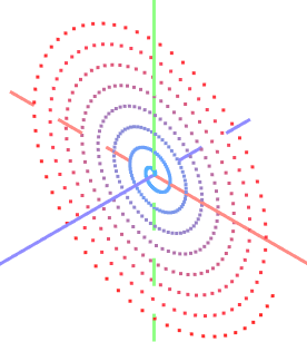
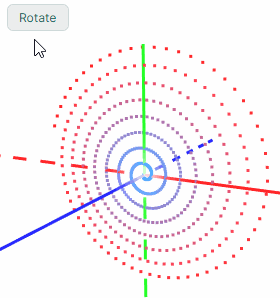
Let's create a point mesh that forms a spiral, in which points are arranged in the XY plane.
int pointCount = 500;

GeometryModel3D model = new GeometryModel3D();
g3DControl.Models.Add(model);
var vertices = new Vertex3D[pointCount];
var indices = new uint[pointCount];
MeshGeometry3D meshPoints = new MeshGeometry3D();
meshPoints.PrimitiveSize = 3;
meshPoints.MaterialKey = "pointsMaterial";
meshPoints.FillType = MeshFillType.Points;
double radius = 0;
double angle = 0;
double radiusStep = 0.1;
double angleStep = 0.1;
for (uint i = 0; i < pointCount; i++)
{
    double x = radius * Math.Cos(angle);
    double y = radius * Math.Sin(angle);
    vertices[i] = new Vertex3D() {
        // Vertex coordinates:
        Position = new Vector3((float)x, (float)y, 0),
        // Normalized coordinates of a position in the texture mapped to the current vertex:
        TextureCoord= new Vector2((float)i/pointCount, 0)
    };
    radius += radiusStep;
    angle += angleStep;
    indices[i] = i;
}
meshPoints.Vertices = vertices;
meshPoints.Indices = indices;
model.Meshes.Add(meshPoints);
You can colorize vertices in a point mesh with different colors. For instance, vertices can be painted with colors determined by their positions or coordinates.
The code below shows how to use a textured material to colorize vertices. The index of a vertex determines its color (the position in the following color gradient).

Add a textured material (
TexturedPbrMaterial) to theGraphics3DControl.Materialscollection. A textured material represents a set of bitmaps that specify the following texture settings:Albedo— Base colorAlpha— TransparencyEmission— Intensity of light emitted from the surfaceAmbientOcclusion— Level of the shadowing caused by objects blocking the ambient lightRoughness— Smoothness of the surfaceMetallic— Reflectivity of the surface settings
Vertices are later mapped to specific positions within these texture bitmaps.
To ensure that the vertices display the realistic colors from the target color gradient, configure the texture bitmaps as follows:
- Set
TexturedPbrMaterial.Emissionto the gradient bitmap that determines the real color of the vertices. - Set
TexturedPbrMaterial.Albedoto a bitmap filled with black. - Set
TexturedPbrMaterial.RoughnessandTexturedPbrMaterial.AmbientOcclusionto bitmaps that are filled with white.
using DynamicData;
using Avalonia.Media;

public void InitG3DControlMaterials()
{
    g3DControl.Materials.AddRange(
        new[] {
            new TexturedPbrMaterial(){
                Albedo = getSolidColorBitmap(Colors.Black),
                Roughness = getSolidColorBitmap(Colors.White),
                AmbientOcclusion = getSolidColorBitmap(Colors.White),
                Emission = getGradientColorBitmap(Colors.DodgerBlue, Colors.Red),
                Key= "pointsMaterial"
            }
        }
    );
}

Bitmap getSolidColorBitmap(Color fillColor)
{
    var bitmap = new RenderTargetBitmap(new PixelSize(pointCount, 1));
    using (var context = bitmap.CreateDrawingContext())
    {
        Brush brush = new SolidColorBrush(fillColor);
        context.FillRectangle(brush, new Rect(0, 0, pointCount, 1));
    }
    return bitmap;
}

Bitmap getGradientColorBitmap(Color fillColor1, Color fillColor2)
{
    var bitmap = new RenderTargetBitmap(new PixelSize(pointCount, 1));
    using (var context = bitmap.CreateDrawingContext())
    {
        var gradientBrush = new LinearGradientBrush
        {
            StartPoint = new RelativePoint(0, 0, RelativeUnit.Relative),
            EndPoint = new RelativePoint(1, 1, RelativeUnit.Relative),
            GradientStops = {
                new GradientStop(fillColor1, 0.0),
                new GradientStop(fillColor2, 1.0)
            }
        };

        context.FillRectangle(gradientBrush, new Rect(0, 0, pointCount, 1));
    }
    return bitmap;
}
The material's
TexturedPbrMaterial.Keyproperty is set to a unique key (string). Unique keys allow identification of materials in theGraphics3DControl.Materialscollection.Assign the created material to the mesh using the
MeshGeometry3D.MaterialKeyproperty. TheMeshGeometry3D.MaterialKeyproperty should match the value of theTexturedPbrMaterial.Keysetting.meshPoints.MaterialKey = "pointsMaterial";Use the
Vertex3D.TextureCoordproperty to map vertices to specific positions in the texture. This property should specify normalized coordinates. The TextureCoord.X and TextureCoord.Y values should be in the range between 0 and 1, where 0 corresponds to the left or top edge of the texture bitmap, and 1 corresponds to the right or bottom edge of the texture bitmap.When vertices are created, specify the
Vertex3D.TextureCoordproperty to address target positions in the texture.vertices[i] = new Vertex3D() { // Vertex coordinates: Position = new Vector3((float)x, (float)y, 0), // Normalized coordinates of a position in the texture mapped to the current vertex: TextureCoord= new Vector2((float)i/pointCount, 0) };Now the vertices are colorized using the specified gradient.
Thickness of Points
In a point mesh, use the PrimitiveSize property to change the thickness of points.
Model Visibility
Use the GeometryModel3D.Visible property to temporarily hide and then restore a model.
GeometryModel3D model = new GeometryModel3D();
g3DControl.Models.Add(model);
//...
model.Visible = !model.Visible;
Model Transformations
The Graphics3DControl allows you to perform transformations on models. For this purpose, construct a transformation matrix that rotates, scales and/or translates the model. Once created, assign this matrix to the GeometryModel3D.Transform property.
To clear the current transformation, set the GeometryModel3D.Transform property to a Matrix4x4.Identity object.
The Matrix4x4 class provides methods to generate transformation matrices for various types of transformations. Some of these methods include:
Matrix4x4.CreateRotationX— Generates a transformation matrix that represents a rotation around the X-axis by a specified angle.Matrix4x4.CreateRotationY— Generates a transformation matrix that represents a rotation around the Y-axis by a specified angle.Matrix4x4.CreateRotationZ— Generates a transformation matrix that represents a rotation around the Z-axis by a specified angle.Matrix4x4.CreateTranslation— Generates a transformation matrix that moves an object by a specified offset along the X, Y, and Z axes.Matrix4x4.CreateScale— Generates a transformation matrix that scales an object along the X, Y, and Z axes.
To apply multiple transformations at the same time, you can multiply matrices that preform individual transformations.
Example - Rotate a model
The following example creates an animation that rotates a 3D model (a spiral consisting of points). The Matrix4x4.CreateRotationZ method is called to generate a transformation matrix that rotates the model by a specified angle around the Z axis.
To apply the transformation, this matrix is assigned to the GeometryModel3D.Transform property.
GeometryModel3D model;
//Init the model
//...
float angleStep = MathF.PI / 180;
float angle = 0;

private void BtnRotate_Click(object? sender, Avalonia.Interactivity.RoutedEventArgs e)
{
    for (int i = 0; i < 180; i++)
    {
        angle += angleStep;
        Matrix4x4 rotationMatrix = Matrix4x4.CreateRotationZ(angle);
        model.Transform = rotationMatrix;
        // Update the UI
        Dispatcher.UIThread.RunJobs();
        Thread.Sleep(12);
    }
}
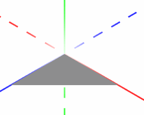
Example - Perform multiple transformations
The following example creates a 3D model that renders a triangle, and shows how to perform multiple transformations on the model.
The example combines scaling, rotation and translation operations into a single transformation matrix, and then assigns this matrix to the GeometryModel3D.Transform property to apply the transformations.
The example applies small incremental changes to the transformation matrices, creating a smooth animation effect.
xmlns:mx3d="https://schemas.eremexcontrols.net/avalonia/controls3d"

<mx3d:Graphics3DControl Name="g3DControl" ShowAxes="True" Grid.Row="1"/>
using DynamicData;

public MainWindow()
{
    InitG3dControl();
}

private void InitG3dControl()
{
    // Create a 3D model that renders a triangle.
    GeometryModel3D model = new GeometryModel3D();
    g3DControl.Models.Add(model);
    Vector3 pt1 = new(1f, 0, 0);
    Vector3 pt2 = new(0, 0, 0);
    Vector3 pt3 = new(0, 0, 1);
    MeshGeometry3D meshSquare = new MeshGeometry3D();
    meshSquare.FillType = MeshFillType.Triangles;
    Vertex3D[] meshSquareVertices = new Vertex3D[]
    {
        new Vertex3D() { Position = pt1,  Normal = new Vector3(0, 1, 0) },
        new Vertex3D() { Position = pt2,  Normal = new Vector3(0, 1, 0) },
        new Vertex3D() { Position = pt3,  Normal = new Vector3(0, 1, 0) }
    };
    uint[] meshSquareIndices = new uint[] { 0, 1, 2 };
    meshSquare.Indices = meshSquareIndices;
    meshSquare.Vertices = meshSquareVertices;
    model.Meshes.AddRange(new[] { meshSquare });
    this.model = model;
}

//Transform the model
private void BtnRotate_Click(object? sender, Avalonia.Interactivity.RoutedEventArgs e)
{
    int steps = 100;
    Vector3 stepTranslationVector = new Vector3(-0.5f, 0, 0)/steps;
    Vector3 stepScaleVector = new Vector3(-0.5f, 0, 0.1f)/steps;
    float stepRotationAngle = (MathF.PI/2)/steps;

    Vector3 translationVector = new Vector3(0,0,0),
        scaleVector = new Vector3(1, 1, 1);
    float rotationAngle = 0;

    for (int i = 0; i < steps; i++)
    {
        rotationAngle += stepRotationAngle;
        translationVector += stepTranslationVector;
        scaleVector += stepScaleVector;

        // Translation Matrix (move by)
        Matrix4x4 translationMatrix = Matrix4x4.CreateTranslation(translationVector);
        // Scaling Matrix
        Matrix4x4 scalingMatrix = Matrix4x4.CreateScale(scaleVector);
        // Rotation Matrix
        Matrix4x4 rotationMatrix = Matrix4x4.CreateRotationY(rotationAngle);
        rotationMatrix *= Matrix4x4.CreateRotationX(rotationAngle);

        Matrix4x4 combinedMatrix = Matrix4x4.Identity;
        combinedMatrix *= scalingMatrix;
        combinedMatrix *= rotationMatrix;
        combinedMatrix *= translationMatrix;

        model.Transform = combinedMatrix;
        // Update the UI
        Dispatcher.UIThread.RunJobs();
        Thread.Sleep(12);
    }
}
Multisampling (Anti-aliasing)
Graphics3DControl.MultisamplingMode— Activates multisample anti-aliasing (MSAA) or disables it.
The anti-aliasing feature is used to reduce visual artifacts, such as jagged edges (aliasing), in rendered graphics, producing smoother and more refined results.
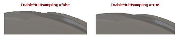
The MultisamplingMode property can be set to the following values: None, X2, X4, X8, X16, X32, X64. The X2...X64 values determine the number of sample points per pixel to calculate the final color of a pixel. More samples lead to better results, however it is also more computationally expensive.
- The
MultisamplingModeproperty's default value isX8. - Not all MSAA modes may be supported by your GPU. If an unsupported MSAA mode is chosen, the system falls back to a lower available mode. You can use the
Graphics3DControl.AvailableMultisamplingModesproperty to return a list of MSAA modes supported by your graphics driver. - Multisampling for large 3D models increases memory usage and computational costs. To improve application performance in such cases, consider setting the
MultisamplingModeto a lower value or disabling MSAA.
Materials
Each mesh in a Graphics3DControl control can be painted with its own material. A material specifies how surfaces interact with light, giving objects their visual appearance.
The Graphics3DControl control supports two material types:
SimplePbrMaterial— A material that defines the visual properties of a surface using numeric values, such as colors (e.g., albedo and emission) and light interaction settings (e.g., metallic and roughness). For more information see Simple Materials (SimplePbrMaterial)TexturedPbrMaterial— A textured material in PBR format. This material specifies the visual properties of a surface using textures (bitmaps). For more information see Textured Materials (TexturedPbrMaterial)
To apply materials to meshes, do the following:
- Create and initialize materials.
- Set the
Keyproperty for the materials to unique strings. The keys allow for material identification when assigning the materials to meshes. - Add the materials to the
Graphics3DControl.Materialscollection. - Use the
MeshGeometry3D.MaterialKeyproperty to associate a mesh with a specific material. For this purpose, set theMeshGeometry3D.MaterialKeyproperty to theKeyproperty of the target material.
Example - Assign a material to a mesh
The following example creates three materials (SimplePbrMaterial objects), and applies one of these materials to a mesh. The materials created are identified by unique string keys ("BrownColor", "TomatoColor" and "VioletColor").
using DynamicData;

g3DControl.Materials.AddRange(
    new[] {
        new SimplePbrMaterial(Color.FromUInt32(0xFF822c2e), "BrownColor"),
        new SimplePbrMaterial(Color.FromUInt32(0xffeb523f), "TomatoColor"),
        new SimplePbrMaterial(Color.FromUInt32(0xFFea3699), "VioletColor")
    }
);

//...

mesh1.MaterialKey = "VioletColor";
Simple Materials (SimplePbrMaterial)
SimplePbrMaterial is a material that describes the visual properties of a surface as numeric values. It provides the following members to specify the visual settings:
Albedo— The base color.The property's value is a Vector3 object whose X, Y and Z members specify normalized values for the Red, Green and Blue color components. Normalized values fall in the range [0;1]. To convert a standard color component (0–255) to a normalized value, divide it by 255. You can also use the
SimplePbrMaterialconstructor to initialize theAlbedoandAlphaproperties from a specifiedColorobject. This constructor automaticaly normalizes the color components.Alpha— The transparency level.The property's value should be in the range [0;1], where
0means fully transparent, and1means fully opaque.Emission— Intensity of light emitted from the surface.The property's value is a Vector3 object whose X, Y and Z members specify normalized values for the Red, Green and Blue color components. Normalized values fall in the range [0;1]. To convert a standard color component (0–255) to a normalized value, divide it by 255.
AmbientOcclusion— Level of the shadowing caused by objects blocking the ambient light.The property's value should be in the range [0;1], where
0means that the maximum effect of ambient occlusion is applied, and1means that no ambient occlusion is applied.Roughness— Smoothness of the surface.The property's value should be in the range [0;1], where
0means a perfectly smooth and glossy surface, and1means a completely rough and matte surface.Metallic— Reflectivity of the surface.The property's value should be in the range [0;1], where
0means a non-metallic surface, and1means a fully metallic material.
Demo
The Simple Materials example in the demo application demonstrates a 3D model painted using a simple material. The demo allows you to adjust the material's settings in real time and instantly see the effects of your changes.
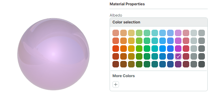
Example - Apply a simple material to a model
The following code creates a simple material (SimplePbrMaterial object) and applies it to the first mesh of a 3D model.
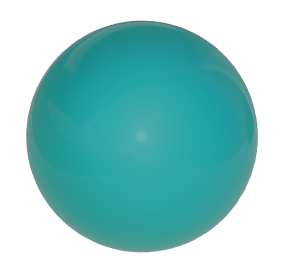
The SimplePbrMaterial.Albedo property is set to the base color (Teal), using normalized color coordinates.
SimplePbrMaterial material = new SimplePbrMaterial();
material.Albedo = ToNormalizedVector3(Colors.Teal);
material.Emission = ToNormalizedVector3(Colors.Black);
material.Metallic = 0;
material.Roughness = 0.5f;
material.AmbientOcclusion = 1;
material.Key = "myFavMaterial";
g3DControl.Materials.Add(material);

// Apply the material to the first mesh of the model
g3DControl.Models[0].Meshes[0].MaterialKey = "myFavMaterial";


public static Vector3 ToNormalizedVector3(Color color)
{
    return new Vector3(color.R/255f, color.G/255f, color.B/255f);
}
This material, when applied to a sample 3D model, is shown below:
Textured Materials (TexturedPbrMaterial)
TexturedPbrMaterial is a material that uses PBR textures (bitmaps) to define the visual properties of a surface. The TexturedPbrMaterial class provides the following members to configure the material's settings:
Albedo— A bitmap that specifies the base color of the material.Alpha— A bitmap that specifies the transparency level.Emission— A bitmap that specifies the intensity of light emitted from the surface.AmbientOcclusion— A bitmap that specifies the level of the shadowing caused by objects blocking the ambient light.Roughness— A bitmap that specifies smoothness of the surface.Metallic— A bitmap that specifies reflectivity of the surface.Normal— A bitmap that specifies a Normal Map.
Demo
The Textured Materials example in the demo application demonstrates a 3D model rendered using PBR textures. The textures are loaded from graphic files stored in the application's resources.
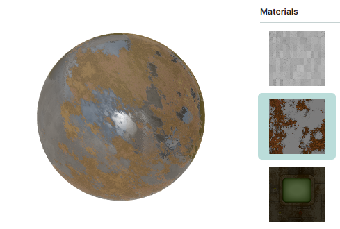
The following code snippet from the Textured Materials demo populates a View Model's Materials collection with materials (TexturedPbrMaterial objects). These materials are created for all textures that are stored as ZIP files in the application's resources, located in the DemoCenter.Resources.Graphics3D.Materials folder. For each material, if a ZIP file with a texture contains bitmaps for the Albedo, AmbientOcclusion, Metallic, Roughness, Normal and Emission settings, these bitmaps are loaded and applied to the material.
public partial class Graphics3DControlTexturedMaterialsViewModel : Graphics3DControlViewModel
{
    [ObservableProperty] ObservableCollection<TexturedPbrMaterial> materials = new();
    [ObservableProperty] TexturedPbrMaterial selectedMaterial;

    public Graphics3DControlTexturedMaterialsViewModel()
    {
        var assembly = Assembly.GetAssembly(typeof(Graphics3DControlViewModel));
        var textureNames = assembly!.GetManifestResourceNames().Where(name => name.StartsWith("DemoCenter.Resources.Graphics3D.Materials."));
        foreach (var textureName in textureNames)
            materials.Add(LoadMaterial(assembly, textureName));
        selectedMaterial = Materials.First();
        //...
    }

    static TexturedPbrMaterial LoadMaterial(Assembly assembly, string resourceName)
    {
        var stream = assembly!.GetManifestResourceStream(resourceName);
        using var archive = new ZipArchive(stream!, ZipArchiveMode.Read);
        var material = new TexturedPbrMaterial { Key = resourceName.Split('.')[^2] };
        foreach (var entry in archive.Entries)
        {
            using var entryStream = entry.Open();
            using var memoryStream = new MemoryStream();
            entryStream.CopyTo(memoryStream);
            memoryStream.Seek(0, SeekOrigin.Begin);
            var bitmap = new Bitmap(memoryStream);
            if (entry.Name.StartsWith("Albedo"))
                material.Albedo = bitmap;
            else if (entry.Name.StartsWith("AO"))
                material.AmbientOcclusion = bitmap;
            else if (entry.Name.StartsWith("Metallic"))
                material.Metallic = bitmap;
            else if (entry.Name.StartsWith("Roughness"))
                material.Roughness = bitmap;
            else if (entry.Name.StartsWith("Normal"))
                material.Normal = bitmap;
            else if (entry.Name.StartsWith("Emissive"))
                material.Emission = bitmap;
        }
        return material;
    }
}
The XAML code below from the Textured Materials demo binds a Graphics3DControl control to the collection of materials in the View Model (Graphics3DControlTexturedMaterialsViewModel.Materials). The material currently applied is specified by the Graphics3DControlTexturedMaterialsViewModel.SelectedMaterial property.
<mx3d:Graphics3DControl x:Name="DemoControl" MaterialsSource="{Binding Materials}">
    <mx3d:GeometryModel3D>
        <mx3d:MeshGeometry3D Vertices="{Binding Vertices}" Indices="{Binding Indices}" MaterialKey="{Binding SelectedMaterial.Key}" />
    </mx3d:GeometryModel3D>
</mx3d:Graphics3DControl>
Texture Coordinates
When you use a textured material, you need to map the texture to a surface. For this purpose, initialize the Vertex3D.TextureCoord property of vertices in your mesh. This property specifies texture coordinates (often referred to as UV coordinates).
Texture coordinates are 2D coordinates (x, y) to which a vertice is mapped.
xrepresents a horizontal coordinate in the texture, in the range [0; 1], where0represents the left edge, and1represents the right edge of the image.yrepresents the vertical coordinate in the texture, in the range [0; 1], where0represents the top edge, and1represents the bottom edge of the image.
For example, an (x, y) coordinate of (0.5, 0.5) would sample the pixel at the center of the texture.
Examples
Examples that demonstrate the use of the Vertex3D.TextureCoord property:
Textured Materialsdemo.Example in the Define a Point Mesh section in the current documentation.
Back-face and Front-face Culling
The Graphics3DControl.CullMode property allows you to enable back-face and front-face culling for triangle meshes. Cull mode determines which faces of a 3D model should be drawn and which should be discarded. You can set the Graphics3DControl.CullMode property to the following values:
CullMode.Back— Enables back-face culling, in which back faces of the triangles are not drawn.CullMode.Front— Enables front-face culling, in which front faces of the triangles are not drawn.CullMode.None— Front and back faces are drawn.
Identify Back and Front of Faces
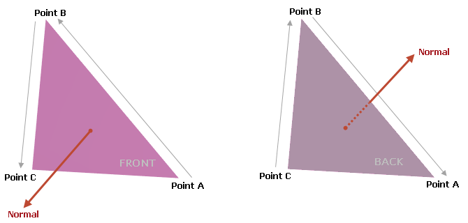
When you define triangular faces for a mesh you use the MeshGeometry3D.Indices property to specify the indices of the vertices that form each triangle.
The order of indices for each mesh triangle is important, as it determines the surface normal direction, and so the front and back of the triangle:
If the indices of a triangle are enumerated counter-clockwise, the surface normal points toward the viewer, and the viewer is seeing the front of the triangle.
If the indices of a triangle are enumerated clockwise, the surface normal points away from the viewer, and the viewer is seeing the back of the triangle.
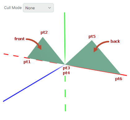
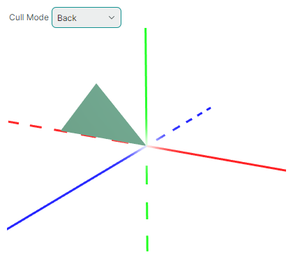
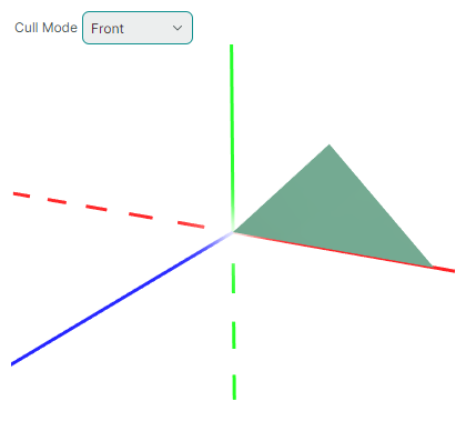
Example
This example demonstrates the face culling feature. In this example, a model that consists of two triangles is created. When displayed, the viewer is seeing the front of the first (left) triangle and back of the second (right) triangle.
xmlns:mx3d="https://schemas.eremexcontrols.net/avalonia/controls3d"

<mx3d:Graphics3DControl Name="g3DControl" ShowAxes="True"/>
using Avalonia.Media;
using DynamicData;

GeometryModel3D model = new GeometryModel3D();
g3DControl.Models.Add(model);

Vector3 pt1 = new(-1f, 0, 0);
Vector3 pt2 = new(-0.5f, 0.5f, 0);
Vector3 pt3 = new(0, 0, 0);
Vector3 pt4 = new(0, 0, 0);
Vector3 pt5 = new(0.5f, 0.5f, 0);
Vector3 pt6 = new(1f, 0, 0);

MeshGeometry3D mesh1 = new MeshGeometry3D();
mesh1.FillType = MeshFillType.Triangles;
Vertex3D[] meshVertices = new Vertex3D[]
{
    new Vertex3D() { Position = pt1,  Normal = new Vector3(0, 0, 1) },
    new Vertex3D() { Position = pt2,  Normal = new Vector3(0, 0, 1) },
    new Vertex3D() { Position = pt3,  Normal = new Vector3(0, 0, 1) },
    new Vertex3D() { Position = pt4,  Normal = new Vector3(0, 0, -1) },
    new Vertex3D() { Position = pt5,  Normal = new Vector3(0, 0, -1) },
    new Vertex3D() { Position = pt6,  Normal = new Vector3(0, 0, -1) }
};
mesh1.Vertices = meshVertices;
// Vertices of the first triangle are enumerated counter-clockwise (pt3->pt2->pt1),
// while vertices of the second triangle are enumerated clockwise (pt4->pt5->pt6):
uint[] meshIndices = new uint[] { 2, 1, 0, 3, 4, 5 };
mesh1.Indices = meshIndices;
model.Meshes.AddRange(new MeshGeometry3D[] { mesh1 });
g3DControl.Materials.Add(new SimplePbrMaterial(Colors.SeaGreen, "myMaterial"));
mesh1.MaterialKey = "myMaterial";
When you set the Graphics3DControl.CullMode property to CullMode.Back, back faces are not drawn. The second (right) triangle is facing away from the camera, so it is not drawn.
When Graphics3DControl.CullMode equals to CullMode.Front, front faces are not drawn. The first (left) triangle is facing toward the camera, so it is hidden:
Gamma and Exposure Corrections
Graphics3DControl.Exposure— Controls the exposure correction level, which adjusts the brightness of the rendered image. The default value is 4.5. The property can be set to a non-negative value.Graphics3DControl.Gamma— Controls gamma correction. The default value is 2.2, which is the standard gamma value for most displays. This property can be set to a non-negative value.