Graphics3DControl 入门
本教程演示如何创建 3D 模型并在 Graphics3DControl 控件中显示它。该示例使用控件公开的 API 来定义网格、顶点和材质。
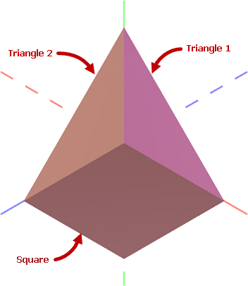
您可以在一个 Graphics3DControl 中同时显示多个 3D 模型。本教程创建一个 3D 模型,它由一个正方形和两个相互成直角放置的三角形组成。每个图形都使用其自己的材质进行绘制。
前提条件:为 Graphics3DControl 注册绘制主题
从 1.3 版本开始,Graphics3DControl 的通用外观设置由 Controls3D 绘制主题指定。这些设置包括控件的对齐方式、可获得焦点状态、背景和边框颜色、Gizmo 设置等。Controls3D 绘制主题与 Graphics3DControl 控件本身定义在同一个程序集中。为确保 Graphics3DControl 正确渲染,您需要在 App.xaml 文件中注册此主题,如下所示:
-
打开 App.xaml 文件,并将以下命名空间添加到
Application对象中: -
在
Application.Styles集合中包含<theme3D:Controls3DTheme/>项。<!-- App.xaml file --> <Application xmlns="https://github.com/avaloniaui" xmlns:x="http://schemas.microsoft.com/winfx/2006/xaml" x:Class="MyEMXCameraApp.App" xmlns:theme="clr-namespace:Eremex.AvaloniaUI.Themes.DeltaDesign;assembly=Eremex.Avalonia.Themes.DeltaDesign" xmlns:theme3D="clr-namespace:Eremex.AvaloniaUI.Themes.Controls3D;assembly=Eremex.Avalonia.Controls3D" RequestedThemeVariant="Default"> <Application.Styles> <theme:DeltaDesignTheme/> <theme3D:Controls3DTheme /> </Application.Styles> </Application>
Note
如果未注册 Controls3D 绘制主题,Graphics3DControl 将显示为空白。
创建 Graphics3DControl
使用以下代码在 XAML 中创建 Graphics3DControl 控件:
xmlns:mx3d="https://schemas.eremexcontrols.net/avalonia/controls3d"

<mx3d:Graphics3DControl Name="g3DControl" ShowAxes="True">
    <mx3d:Graphics3DControl.Camera>
        <mx3d:IsometricCamera/>
    </mx3d:Graphics3DControl.Camera>
</mx3d:Graphics3DControl>
此代码为 Graphics3DControl 控件显示坐标轴并启用等距相机。您也可以启用透视相机。为此,请将 Graphics3DControl.Camera 属性设置为 PerspectiveCamera 对象。
定义 3D 模型
GeometryModel3D 类封装了 Graphics3DControl 的一个 3D 模型。要向控件添加 3D 模型,请将一个或多个 GeometryModel3D 对象添加到 Graphics3DControl.Models 集合中。
using Eremex.AvaloniaUI.Controls3D;

GeometryModel3D model = new GeometryModel3D();
g3DControl.Models.Add(model);
一个 3D 模型由一个或多个网格组成。网格是使用特定材质绘制的模型的一部分。
3D 模型中的正方形和三角形图形使用各自的材质绘制,因此需要创建三个网格。
添加网格
使用 GeometryModel3D.Meshes 集合来添加网格。每个网格由一个 MeshGeometry3D 对象封装。
using DynamicData;

MeshGeometry3D meshTriangle1 = new MeshGeometry3D();
MeshGeometry3D meshTriangle2 = new MeshGeometry3D();
MeshGeometry3D meshSquare = new MeshGeometry3D();
//...
model.Meshes.AddRange(new[] { meshTriangle1, meshTriangle2, meshSquare });
Graphics3DControl 支持三种网格类型:
- 由一组三角形定义的网格(默认,或当
MeshGeometry3D.FillType设置为MeshFillType.Triangles时) - 由一组线段定义的网格(当
MeshGeometry3D.FillType设置为MeshFillType.Lines时) - 由一组点定义的网格(当
MeshGeometry3D.FillType设置为MeshFillType.Points时)
在当前示例中,网格由三角形创建。对于此网格类型,您需要指定以下属性:
-
MeshGeometry3D.Vertices— 构成网格的所有顶点(Vertex3D对象)的数组。Vertex3D对象公开以下主要属性:Vertex3D.Position— 指定顶点坐标的Vector3对象。Vertex3D.Normal— 指定顶点法线的Vector3对象。顶点法线是用于计算顶点和三角形光反射的方向向量。Vertex3D.TextureCoord— 指定当前顶点纹理坐标的Vector2对象。
-
MeshGeometry3D.Indices—Vertices数组中顶点的索引数组,用于定义各个网格三角形。此数组包含若干组,每组三个索引。数组中的前三个索引指向第一个网格三角形的顶点。接下来的三个索引指向第二个网格三角形的顶点,依此类推。 每个三角形索引的顺序很重要,因为它决定了表面法线。表面法线又决定了三角形的正面和背面,这对于背面剔除和正面剔除等操作至关重要。
定义 Triangle 1 和 Triangle 2 图形的网格
Triangle 1 和 Triangle 2 图形的网格很容易定义,因为这些图形本身就是三角形。
首先,让我们确定创建的 3D 模型中的所有顶点及其 (x, y, z) 坐标。
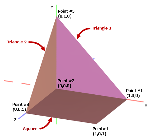
在代码中,使用 Vector3 对象定义所有顶点的坐标:
Vector3 pt1 = new(1, 0, 0);
Vector3 pt2 = new(0, 0, 0);
Vector3 pt3 = new(0, 0, 1);
Vector3 pt4 = new(1, 0, 1);
Vector3 pt5 = new(0, 1, 0);
初始化 Triangle 1 图形的顶点和索引:
Vertex3D[] meshTriangle1Vertices = new Vertex3D[]
{
    new Vertex3D() { Position = pt2,  Normal = new Vector3(0, 0, 1) },
    new Vertex3D() { Position = pt5,  Normal = new Vector3(0, 0, 1) },
    new Vertex3D() { Position = pt1,  Normal = new Vector3(0, 0, 1) },
};

// Define a mesh triangle.
uint[] meshTriangle1Indices = new uint[] { 0, 1, 2 };

meshTriangle1.Vertices = meshTriangle1Vertices;
meshTriangle1.Indices = meshTriangle1Indices;
这里,索引 0、1 和 2 分别指向 Vertices 数组中的第一、第二和第三个顶点。
同样地,初始化 Triangle 2 图形的顶点和索引:
Vertex3D[] meshTriangle2Vertices = new Vertex3D[]
{
    new Vertex3D() { Position = pt2,  Normal = new Vector3(1, 0, 0) },
    new Vertex3D() { Position = pt5,  Normal = new Vector3(1, 0, 0) },
    new Vertex3D() { Position = pt3,  Normal = new Vector3(1, 0, 0) }
};

// Define a mesh triangle.
uint[] meshTriangle2Indices = new uint[] { 0, 1, 2 };

meshTriangle2.Vertices = meshTriangle2Vertices;
meshTriangle2.Indices = meshTriangle2Indices;
定义 Square 图形的网格
Square 图形可以划分为两个网格三角形。例如:
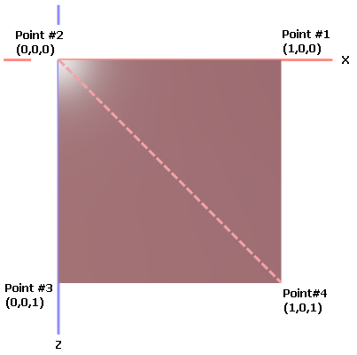
Square 网格的 Vertices 数组应包含四个点。Indices 数组应包含六个索引,用于标识两个网格三角形。
Vertex3D[] meshSquareVertices = new Vertex3D[]
{
    new Vertex3D() { Position = pt1,  Normal = new Vector3(0, 1, 0) },
    new Vertex3D() { Position = pt2,  Normal = new Vector3(0, 1, 0) },
    new Vertex3D() { Position = pt3,  Normal = new Vector3(0, 1, 0) },
    new Vertex3D() { Position = pt4,  Normal = new Vector3(0, 1, 0) }
};

// Define two mesh triangles.
// The first mesh triangle is formed by points pt1, pt2 and pt4.
// The second mesh triangle is formed by points pt2, pt3 and pt4.
uint[] meshSquareIndices = new uint[] { 0, 1, 3, 1, 2, 3 };

meshSquare.Vertices = meshSquareVertices;
meshSquare.Indices = meshSquareIndices;
指定材质
Graphics3DControl 控件支持以下派生自 Eremex.AvaloniaUI.Controls3D.Material 抽象类的材质:
-
SimplePbrMaterial— 一种以数值形式描述表面视觉属性的材质:Albedo— 基础颜色Alpha— 透明度Emission— 表面发光的强度AmbientOcclusion— 由阻挡环境光的物体所造成的阴影级别Roughness— 表面的光滑程度Metallic— 表面的反射率。
-
TexturedPbrMaterial— PBR 格式的纹理材质。此材质允许您以位图形式指定表面的视觉属性(Albedo、Alpha、Emission、AmbientOcclusion、Roughness、Metallic和Normal)。
您需要使用 Material.Key 属性为材质分配唯一的键(字符串值)。
然后,您可以通过 MeshGeometry3D.MaterialKey 属性将材质与网格关联起来。
以下代码添加了三个具有特定基础颜色(Albedo)的材质(SimplePbrMaterial 对象)。创建的网格使用 MaterialKey 属性与材质关联。
using DynamicData;

g3DControl.Materials.AddRange(
    new[] {
        new SimplePbrMaterial(Color.FromUInt32(0xFF822c2e), "BrownColor"),
        new SimplePbrMaterial(Color.FromUInt32(0xffeb523f), "TomatoColor"),
        new SimplePbrMaterial(Color.FromUInt32(0xFFea3699), "VioletColor")
    }
);

//...

meshTriangle1.MaterialKey = "VioletColor";
meshTriangle2.MaterialKey = "TomatoColor";
meshSquare.MaterialKey = "BrownColor";
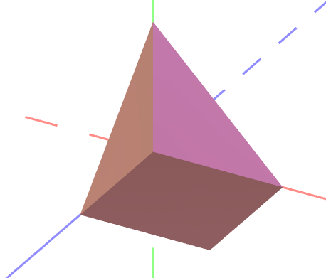
运行应用程序
现在您可以运行应用程序了。使用鼠标和键盘对创建的 3D 模型进行平移、缩放和旋转。
完整代码
<mx:MxWindow xmlns="https://github.com/avaloniaui"
        xmlns:x="http://schemas.microsoft.com/winfx/2006/xaml"
        xmlns:vm="using:G3DControl_Get_Started.ViewModels"
        xmlns:d="http://schemas.microsoft.com/expression/blend/2008"
        xmlns:mc="http://schemas.openxmlformats.org/markup-compatibility/2006"
        xmlns:mx="https://schemas.eremexcontrols.net/avalonia"
        xmlns:mx3d="https://schemas.eremexcontrols.net/avalonia/controls3d"
        xmlns:mxe="https://schemas.eremexcontrols.net/avalonia/editors"

        mc:Ignorable="d" d:DesignWidth="800" d:DesignHeight="450"
        x:Class="G3DControl_Get_Started.Views.MainWindow"
        x:DataType="vm:MainWindowViewModel"
        Icon="/Assets/EMXControls.ico"
        Title="G3DControl_Get_Started">

    <Design.DataContext>
        <!-- This only sets the DataContext for the previewer in an IDE -->
        <vm:MainWindowViewModel/>
    </Design.DataContext>

    <mx3d:Graphics3DControl Name="g3DControl" ShowAxes="True">
        <mx3d:Graphics3DControl.Camera>
            <mx3d:IsometricCamera/>
        </mx3d:Graphics3DControl.Camera>
    </mx3d:Graphics3DControl>
</mx:MxWindow>
using Avalonia.Controls;
using Avalonia.Media;
using DynamicData;
using Eremex.AvaloniaUI.Controls.Common;
using Eremex.AvaloniaUI.Controls3D;
using System;
using System.Numerics;

namespace G3DControl_Get_Started.Views;

public partial class MainWindow : MxWindow
{
    public MainWindow()
    {
        InitializeComponent();

        InitG3DControlMaterials();
        InitG3DControlMeshes();
    }

    private void InitG3DControlMaterials()
    {
        g3DControl.Materials.AddRange(
            new[] {
                new SimplePbrMaterial(Color.FromUInt32(0xFF822c2e), "BrownColor"),
                new SimplePbrMaterial(Color.FromUInt32(0xffeb523f), "TomatoColor"),
                new SimplePbrMaterial(Color.FromUInt32(0xFFea3699), "VioletColor")
            }
        );
    }

    private void InitG3DControlMeshes()
    {

        GeometryModel3D model = new GeometryModel3D();
        g3DControl.Models.Add(model);

        Vector3 pt1 = new(1, 0, 0);
        Vector3 pt2 = new(0, 0, 0);
        Vector3 pt3 = new(0, 0, 1);
        Vector3 pt4 = new(1, 0, 1);
        Vector3 pt5 = new(0, 1, 0);

        // Triangle 1
        MeshGeometry3D meshTriangle1 = new MeshGeometry3D();
        // Setting the FillType property to 'Triangles' is not required
        // as 'Triangles' is the default value of the FillType property.
        //meshTriangle1.FillType = MeshFillType.Triangles;
        Vertex3D[] meshTriangle1Vertices = new Vertex3D[]
        {
            new Vertex3D() { Position = pt2,  Normal = new Vector3(0, 0, 1) },
            new Vertex3D() { Position = pt5,  Normal = new Vector3(0, 0, 1) },
            new Vertex3D() { Position = pt1,  Normal = new Vector3(0, 0, 1) },
        };
        // Define a mesh triangle.
        uint[] meshTriangle1Indices = new uint[] { 0, 2, 1 };
        meshTriangle1.Vertices = meshTriangle1Vertices;
        meshTriangle1.Indices = meshTriangle1Indices;
        meshTriangle1.MaterialKey = "VioletColor";

        // Triangle 2
        MeshGeometry3D meshTriangle2 = new MeshGeometry3D();
        Vertex3D[] meshTriangle2Vertices = new Vertex3D[]
        {
            new Vertex3D() { Position = pt2,  Normal = new Vector3(1, 0, 0) },
            new Vertex3D() { Position = pt5,  Normal = new Vector3(1, 0, 0) },
            new Vertex3D() { Position = pt3,  Normal = new Vector3(1, 0, 0) }
        };
        // Define a mesh triangle.
        uint[] meshTriangle2Indices = new uint[] { 0, 2, 1 };
        meshTriangle2.Vertices = meshTriangle2Vertices;
        meshTriangle2.Indices = meshTriangle2Indices;
        meshTriangle2.MaterialKey = "TomatoColor";

        // Square
        MeshGeometry3D meshSquare = new MeshGeometry3D();
        Vertex3D[] meshSquareVertices = new Vertex3D[]
        {
            new Vertex3D() { Position = pt1,  Normal = new Vector3(0, 1, 0) },
            new Vertex3D() { Position = pt2,  Normal = new Vector3(0, 1, 0) },
            new Vertex3D() { Position = pt3,  Normal = new Vector3(0, 1, 0) },
            new Vertex3D() { Position = pt4,  Normal = new Vector3(0, 1, 0) }
        };
        // Define two mesh triangles.
        // The first mesh triangle is formed by points pt1, pt2 and pt4.
        // The second mesh triangle is formed by points pt2, pt3 and pt4.
        uint[] meshSquareIndices = new uint[] { 0, 1, 3, 1, 2, 3 };
        meshSquare.Vertices = meshSquareVertices;
        meshSquare.Indices = meshSquareIndices;
        meshSquare.MaterialKey = "BrownColor";

        model.Meshes.AddRange(new[] { meshTriangle1, meshTriangle2, meshSquare });
    }
}
* 本页面使用机器翻译技术翻译。