Graphics3DControl 概述
Graphics3DControl 控件允许您在 Avalonia 应用程序中嵌入 3D 模型。该控件支持使用鼠标和键盘执行旋转、平移和缩放操作,让用户能够在运行时与模型进行交互。
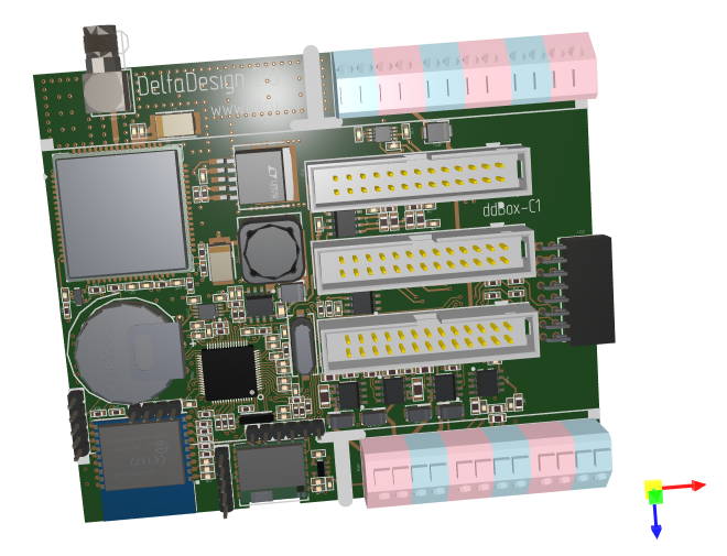
任何 3D 模型都是由使用指定材质渲染的网格组成的。Graphics3DControl 提供了用于定义网格、材质、摄像机和光照设置的 API。您还可以利用第三方库将 OBJ 和 STL 格式的模型加载到 Graphics3DControl 控件中。
主要功能
- 用于指定 3D 模型的 API
- 同时显示多个 3D 模型
- 透视和等距摄像机
- 支持的网格类型:三角形、线和点
- 简单材质和纹理材质
- 3D 模型变换
- 正面和背面剔除
- 支持使用 MVVM 设计模式定义 3D 模型
- 显示坐标轴和网格线
用户交互
- 使用鼠标和键盘旋转、平移和缩放模型
- 提示信息
- 元素高亮和选择
请参阅与 3D 模型的用户交互
快速入门
- Graphics3DControl 快速入门 — 演示如何从零开始创建一个 3D 模型。
演示
请查看 Eremex Avalonia Controls Demo 应用程序,其中包含演示 Graphics3DControl 各种功能的示例:
- 使用第三方库从外部文件加载 Wavefront(Obj)和 Stl 模型,并根据加载的数据创建 3D 模型。
- 从零开始创建 3D 模型。
- 展示支持的网格类型:三角形、线和点。
- 使用 MVVM 设计模式定义 3D 模型,等等。
Graphics3DControl 的绘制主题
从 1.3 版本开始,要使用 Graphics3DControl,您必须在 App.xaml 文件中注册 Controls3D 绘制主题。该主题包含渲染 Graphics3DControl 所需的通用外观设置。有关更多信息,请参阅以下主题:
Note
如果未注册 Controls3D 绘制主题,Graphics3DControl 将显示为空白。
坐标系、坐标轴和网格线
Graphics3DControl 支持右手坐标系(默认)和左手坐标系。您可以使用 Graphics3DControl.CoordinateSystem 属性来启用所需的选项。
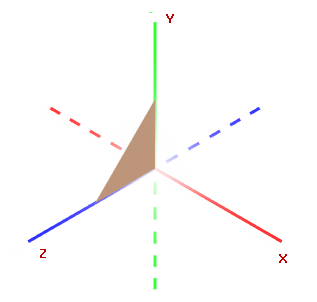
右手坐标系
正 X、Y、Z 轴分别指向右侧、上方和面向观察者的方向。
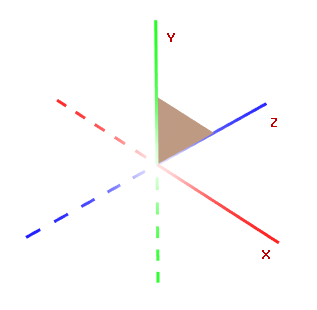
左手坐标系
正 X、Y、Z 轴分别指向右侧、上方和远离观察者的方向。
坐标轴
启用 Graphics3DControl.ShowAxes 属性可在控件中显示 X、Y、Z 坐标轴。
相关选项
Graphics3DControl.AxisThickness属性 — 指定坐标轴的粗细。
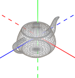
Gizmo
Graphics3DControl 可以显示 Gizmo。它是一个独立的部件,用于直观地指示 3D 空间中坐标轴的当前朝向。
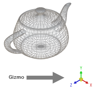
要启用 Gizmo,请使用 Eremex.AvaloniaUI.Controls3D.Gizmo 类的实例初始化 Graphics3DControl.Gizmo 属性。
<mx3d:Graphics3DControl Name="g3DControl" >
        <!-- ... -->
    <mx3d:Graphics3DControl.Gizmo>
        <mx3d:Gizmo Name="gizmo" />
    </mx3d:Graphics3DControl.Gizmo>
</mx3d:Graphics3DControl>
您可以以自定义方式绘制 Gizmo。为此,请使用 Gizmo.Models 或 Gizmo.ModelsSource 属性指定用于渲染 Gizmo 的 3D 模型。填充这些属性的过程与 Graphics3dControl 相同,因为这两个类继承自同一个基类。
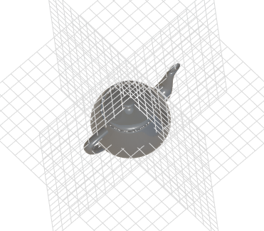
网格线
Graphics3DControl.ShowGrid 属性允许您在 XY、XZ 和 YZ 平面上显示网格线。
](../../images/g3d-grid.png)
相关选项
Graphics3DControl.GridThickness属性 — 指定网格线的粗细。
模型
要为 Graphics3DControl 定义 3D 模型,请使用 Graphics3DControl 的 API 创建表示模型、网格、顶点、材质、摄像机等的对象。
定义 3D 模型
GeometryModel3D 类封装了 Graphics3DControl 中的单个 3D 模型。
使用以下属性之一将 3D 模型添加到控件中:
Graphics3DControl.Models— 一个GeometryModel3D对象的集合。Graphics3DControl.ModelsSource— 按照 MVVM 设计模式,用于创建 3D 模型(GeometryModel3D对象)的业务对象源。
xmlns:mx3d="https://schemas.eremexcontrols.net/avalonia/controls3d"

<mx3d:Graphics3DControl Name="g3DControl" ShowAxes="True"/>
using Eremex.AvaloniaUI.Controls3D;

GeometryModel3D model = new GeometryModel3D();
g3DControl.Models.Add(model);
网格
一个 3D 模型代表使用特定材质渲染的一组网格。网格定义了 3D 对象的形状和结构。
MeshGeometry3D 类表示 Graphics3DControl 中的一个网格。以下属性允许您为模型指定网格:
GeometryModel3D.Meshes— 一个MeshGeometry3D对象的集合。GeometryModel3D.MeshesSource— 按照 MVVM 设计模式,用于创建网格(MeshGeometry3D对象)的业务对象源。
该控件支持三种网格类型,您可以通过 MeshGeometry3D.FillType 属性进行选择。
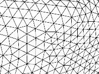
MeshFillType.Triangles(默认)— 三角形网格。由三角形面(由三条边围成的平面区域)组成。
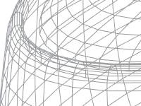
MeshFillType.Lines— 线网格。顶点通过线连接,形成线框。
MeshFillType.Points— 点网格(点云)。由未通过线连接的顶点组成。

using DynamicData;

MeshGeometry3D meshTriangle1 = new MeshGeometry3D();
MeshGeometry3D meshSquare = new MeshGeometry3D();
MeshGeometry3D meshPoints = new MeshGeometry3D() { FillType = MeshFillType.Points };
//Define the meshes
//...
model.Meshes.AddRange(new[] { meshTriangle1, meshSquare, meshPoints });
创建网格时,使用以下属性来定义顶点和面/线:
MeshGeometry3D.Vertices数组 — 指定组成网格的所有顶点的数组。MeshGeometry3D.Indices数组 — 定义三角形面(对于三角形网格),或线(对于线网格)。
顶点
顶点是 3D 空间中由其坐标 (x, y, z) 定义的一个点。
Vertex3D 类型封装了 Graphics3DControl 中的单个顶点。使用 MeshGeometry3D.Vertices 数组向网格添加顶点。
Vertex3D 类型公开了以下需要初始化的主要属性。
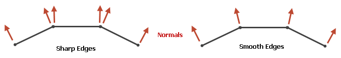
Vertex3D.Position— 一个Vector3值,指定顶点的 (x, y, z) 坐标。Vertex3D.Normal— 一个Vector3值,指定顶点法线。顶点法线是在该顶点处垂直于 3D 模型表面的向量。在 3D 图形中,顶点法线用于计算网格的光照和着色。相邻三角形的法线必须对齐,以确保平滑的着色(边缘)效果。
Vertex3D.TextureCoord— 一个Vector2值,指定纹理材质中映射到当前顶点的点的 (x, y) 坐标。
定义三角形网格
要创建三角形网格,您需要将一个形状划分为若干三角形。顶点指定这些三角形的角点。MeshGeometry3D.FillType 属性需要设置为其默认值(MeshFillType.Triangles)。
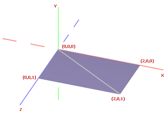
考虑一个网格为四边形的示例。可以通过添加一条对角线将其三角化。
首先,将所有顶点添加到 MeshGeometry3D.Vertices 数组中。
using DynamicData;

GeometryModel3D model = new GeometryModel3D();
g3DControl.Models.Add(model);

Vector3 pt1 = new(2f, 0, 0);
Vector3 pt2 = new(0, 0, 0);
Vector3 pt3 = new(0, 0, 1);
Vector3 pt4 = new(2f, 0, 1);

MeshGeometry3D meshSquare = new MeshGeometry3D();
meshSquare.FillType = MeshFillType.Triangles;
Vertex3D[] meshSquareVertices = new Vertex3D[]
{
    new Vertex3D() { Position = pt1,  Normal = new Vector3(0, 1, 0) },
    new Vertex3D() { Position = pt2,  Normal = new Vector3(0, 1, 0) },
    new Vertex3D() { Position = pt3,  Normal = new Vector3(0, 1, 0) },
    new Vertex3D() { Position = pt4,  Normal = new Vector3(0, 1, 0) }
};
meshSquare.Vertices = meshSquareVertices;
//...
model.Meshes.AddRange(new[] { meshSquare });
然后使用 MeshGeometry3D.Indices 属性来构成三角形面。
对于三角形网格,MeshGeometry3D.Indices 属性是 MeshGeometry3D.Vertices 数组中定义各个网格三角形的顶点索引数组。此数组包含若干组,每组三个索引。数组中的前三个索引指向第一个网格三角形的顶点。接下来的三个索引指向第二个网格三角形的顶点,依此类推。
每个三角形的索引顺序很重要,因为它决定了表面法线。表面法线又决定了三角形的正面和背面,这对于背面剔除和正面剔除等操作至关重要。
对于上面的四边形网格,MeshGeometry3D.Indices 数组应包含六个索引。前三个索引指向第一个三角形的顶点。后三个索引指向第二个三角形的顶点。
定义线网格
在线网格中,顶点通过线连接。要定义线网格,请创建一个 MeshGeometry3D 对象,并将其 MeshGeometry3D.FillType 属性设置为 MeshFillType.Lines。然后使用 MeshGeometry3D.Vertices 属性指定所有顶点,并使用 MeshGeometry3D.Indices 属性将顶点用线连接起来。
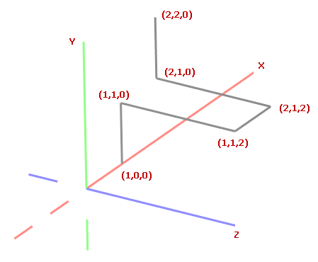
考虑以下由连接六个点的线组成的 3D 模型。
首先,将所有顶点添加到 MeshGeometry3D.Vertices 数组中。
GeometryModel3D model = new GeometryModel3D();
g3DControl.Models.Add(model);

Vector3 p0 = new(1, 0, 0);
Vector3 p1 = new(1, 1, 0);
Vector3 p2 = new(1, 1, 2);
Vector3 p3 = new(2, 1, 2);
Vector3 p4 = new(2, 1, 0);
Vector3 p5 = new(2, 2, 0);

MeshGeometry3D meshLines = new MeshGeometry3D();
meshLines.PrimitiveSize = 3;
meshLines.FillType = MeshFillType.Lines;
Vertex3D[] meshLinesVertices = new Vertex3D[]
{
    new Vertex3D() { Position = p0,  Normal = new Vector3(0, 1, 0) },
    new Vertex3D() { Position = p1,  Normal = new Vector3(0, 1, 0) },
    new Vertex3D() { Position = p2,  Normal = new Vector3(0, 1, 0) },
    new Vertex3D() { Position = p3,  Normal = new Vector3(0, 1, 0) },
    new Vertex3D() { Position = p4,  Normal = new Vector3(0, 1, 0) },
    new Vertex3D() { Position = p5,  Normal = new Vector3(0, 1, 0) }
};
meshLines.Vertices = meshLinesVertices;
//...
model.Meshes.Add(meshLines);
使用 MeshGeometry3D.Indices 属性将顶点用线连接起来。对于线网格,MeshGeometry3D.Indices 属性是 MeshGeometry3D.Vertices 数组中定义各条线的顶点索引数组。
此数组包含成对的索引。数组中前两个索引指向第一条线的顶点。接下来两个索引指向第二条线的顶点,依此类推。
对于上面的示例,MeshGeometry3D.Indices 数组应包含 10 个索引。第一对索引指向定义第一条线的点。第二对索引指向第二条线的顶点,依此类推。
uint[] meshLinesIndices = new uint[] { 0, 1, 1, 2, 2, 3, 3, 4, 4, 5 };
meshLines.Indices = meshLinesIndices;
线的粗细
在线网格中,使用 PrimitiveSize 属性来更改线的粗细。
定义点网格
在点网格中,顶点被渲染为独立的点。
要定义点网格,请创建一个 MeshGeometry3D 对象,并将其 MeshGeometry3D.FillType 属性设置为 MeshFillType.Points。然后使用 MeshGeometry3D.Vertices 属性指定所有顶点,并使用 MeshGeometry3D.Indices 属性指定要渲染哪些顶点。
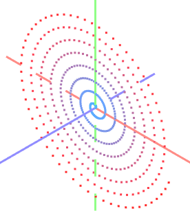
让我们创建一个形成螺旋线的点网格,其中的点排列在 XY 平面上。
int pointCount = 500;

GeometryModel3D model = new GeometryModel3D();
g3DControl.Models.Add(model);
var vertices = new Vertex3D[pointCount];
var indices = new uint[pointCount];
MeshGeometry3D meshPoints = new MeshGeometry3D();
meshPoints.PrimitiveSize = 3;
meshPoints.MaterialKey = "pointsMaterial";
meshPoints.FillType = MeshFillType.Points;
double radius = 0;
double angle = 0;
double radiusStep = 0.1;
double angleStep = 0.1;
for (uint i = 0; i < pointCount; i++)
{
    double x = radius * Math.Cos(angle);
    double y = radius * Math.Sin(angle);
    vertices[i] = new Vertex3D() {
        // Vertex coordinates:
        Position = new Vector3((float)x, (float)y, 0),
        // Normalized coordinates of a position in the texture mapped to the current vertex:
        TextureCoord= new Vector2((float)i/pointCount, 0)
    };
    radius += radiusStep;
    angle += angleStep;
    indices[i] = i;
}
meshPoints.Vertices = vertices;
meshPoints.Indices = indices;
model.Meshes.Add(meshPoints);
您可以使用不同的颜色为点网格中的顶点着色。例如,可以根据顶点的位置或坐标来为其着色。
以下代码展示了如何使用纹理材质为顶点着色。顶点的索引决定了它的颜色(在下方颜色渐变中的位置)。

-
将纹理材质(
TexturedPbrMaterial)添加到Graphics3DControl.Materials集合中。纹理材质表示一组位图,用于指定以下纹理设置:Albedo— 基础颜色Alpha— 透明度Emission— 表面发光的强度AmbientOcclusion— 由阻挡环境光的对象所造成的阴影级别Roughness— 表面的光滑程度Metallic— 表面的反射率设置
顶点随后会被映射到这些纹理位图内的特定位置。
为确保顶点显示出目标颜色渐变中的真实颜色,请按如下方式配置纹理位图:
- 将
TexturedPbrMaterial.Emission设置为决定顶点真实颜色的渐变位图。 - 将
TexturedPbrMaterial.Albedo设置为填充为黑色的位图。 - 将
TexturedPbrMaterial.Roughness和TexturedPbrMaterial.AmbientOcclusion设置为填充为白色的位图。
using DynamicData;
using Avalonia.Media;

public void InitG3DControlMaterials()
{
    g3DControl.Materials.AddRange(
        new[] {
            new TexturedPbrMaterial(){
                Albedo = getSolidColorBitmap(Colors.Black),
                Roughness = getSolidColorBitmap(Colors.White),
                AmbientOcclusion = getSolidColorBitmap(Colors.White),
                Emission = getGradientColorBitmap(Colors.DodgerBlue, Colors.Red),
                Key= "pointsMaterial"
            }
        }
    );
}

Bitmap getSolidColorBitmap(Color fillColor)
{
    var bitmap = new RenderTargetBitmap(new PixelSize(pointCount, 1));
    using (var context = bitmap.CreateDrawingContext())
    {
        Brush brush = new SolidColorBrush(fillColor);
        context.FillRectangle(brush, new Rect(0, 0, pointCount, 1));
    }
    return bitmap;
}

Bitmap getGradientColorBitmap(Color fillColor1, Color fillColor2)
{
    var bitmap = new RenderTargetBitmap(new PixelSize(pointCount, 1));
    using (var context = bitmap.CreateDrawingContext())
    {
        var gradientBrush = new LinearGradientBrush
        {
            StartPoint = new RelativePoint(0, 0, RelativeUnit.Relative),
            EndPoint = new RelativePoint(1, 1, RelativeUnit.Relative),
            GradientStops = {
                new GradientStop(fillColor1, 0.0),
                new GradientStop(fillColor2, 1.0)
            }
        };

        context.FillRectangle(gradientBrush, new Rect(0, 0, pointCount, 1));
    }
    return bitmap;
}
材质的
TexturedPbrMaterial.Key属性被设置为一个唯一的键(字符串)。唯一键用于在Graphics3DControl.Materials集合中识别材质。 -
使用
MeshGeometry3D.MaterialKey属性将创建的材质分配给网格。MeshGeometry3D.MaterialKey属性应与TexturedPbrMaterial.Key设置的值相匹配。 -
使用
Vertex3D.TextureCoord属性将顶点映射到纹理中的特定位置。此属性应指定归一化坐标。TextureCoord.X 和 TextureCoord.Y 的值应在 0 到 1 的范围内,其中 0 对应纹理位图的左边缘或上边缘,1 对应纹理位图的右边缘或下边缘。创建顶点时,指定
Vertex3D.TextureCoord属性,以确定纹理中的目标位置。vertices[i] = new Vertex3D() { // Vertex coordinates: Position = new Vector3((float)x, (float)y, 0), // Normalized coordinates of a position in the texture mapped to the current vertex: TextureCoord= new Vector2((float)i/pointCount, 0) };现在,顶点已使用指定的渐变进行着色。
点的粗细
在点网格中,使用 PrimitiveSize 属性来更改点的粗细。
模型可见性
使用 GeometryModel3D.Visible 属性来临时隐藏,然后再恢复某个模型。
GeometryModel3D model = new GeometryModel3D();
g3DControl.Models.Add(model);
//...
model.Visible = !model.Visible;
模型变换
Graphics3DControl 允许您对模型执行变换。为此,请构造一个用于旋转、缩放和/或平移模型的变换矩阵。创建完成后,将该矩阵赋值给 GeometryModel3D.Transform 属性。
要清除当前的变换,请将 GeometryModel3D.Transform 属性设置为 Matrix4x4.Identity 对象。
Matrix4x4 类提供了用于生成各种类型变换矩阵的方法。其中一些方法包括:
Matrix4x4.CreateRotationX— 生成一个表示绕 X 轴旋转指定角度的变换矩阵。Matrix4x4.CreateRotationY— 生成一个表示绕 Y 轴旋转指定角度的变换矩阵。Matrix4x4.CreateRotationZ— 生成一个表示绕 Z 轴旋转指定角度的变换矩阵。Matrix4x4.CreateTranslation— 生成一个将对象沿 X、Y、Z 轴按指定偏移量移动的变换矩阵。Matrix4x4.CreateScale— 生成一个将对象沿 X、Y、Z 轴进行缩放的变换矩阵。
要同时应用多个变换,您可以将执行各个变换的矩阵相乘。
示例 - 旋转模型
以下示例创建了一个旋转 3D 模型(一个由点组成的螺旋线)的动画。调用 Matrix4x4.CreateRotationZ 方法来生成一个使模型绕 Z 轴旋转指定角度的变换矩阵。
要应用该变换,需将此矩阵赋值给 GeometryModel3D.Transform 属性。
GeometryModel3D model;
//Init the model
//...
float angleStep = MathF.PI / 180;
float angle = 0;

private void BtnRotate_Click(object? sender, Avalonia.Interactivity.RoutedEventArgs e)
{
    for (int i = 0; i < 180; i++)
    {
        angle += angleStep;
        Matrix4x4 rotationMatrix = Matrix4x4.CreateRotationZ(angle);
        model.Transform = rotationMatrix;
        // Update the UI
        Dispatcher.UIThread.RunJobs();
        Thread.Sleep(12);
    }
}
示例 - 执行多个变换
以下示例创建了一个渲染三角形的 3D 模型,并展示了如何对该模型执行多个变换。
该示例将缩放、旋转和平移操作组合成一个变换矩阵,然后将此矩阵赋值给 GeometryModel3D.Transform 属性以应用这些变换。
该示例对变换矩阵应用小幅度的渐进变化,从而创建出平滑的动画效果。
xmlns:mx3d="https://schemas.eremexcontrols.net/avalonia/controls3d"

<mx3d:Graphics3DControl Name="g3DControl" ShowAxes="True" Grid.Row="1"/>
using DynamicData;

public MainWindow()
{
    InitG3dControl();
}

private void InitG3dControl()
{
    // Create a 3D model that renders a triangle.
    GeometryModel3D model = new GeometryModel3D();
    g3DControl.Models.Add(model);
    Vector3 pt1 = new(1f, 0, 0);
    Vector3 pt2 = new(0, 0, 0);
    Vector3 pt3 = new(0, 0, 1);
    MeshGeometry3D meshSquare = new MeshGeometry3D();
    meshSquare.FillType = MeshFillType.Triangles;
    Vertex3D[] meshSquareVertices = new Vertex3D[]
    {
        new Vertex3D() { Position = pt1,  Normal = new Vector3(0, 1, 0) },
        new Vertex3D() { Position = pt2,  Normal = new Vector3(0, 1, 0) },
        new Vertex3D() { Position = pt3,  Normal = new Vector3(0, 1, 0) }
    };
    uint[] meshSquareIndices = new uint[] { 0, 1, 2 };
    meshSquare.Indices = meshSquareIndices;
    meshSquare.Vertices = meshSquareVertices;
    model.Meshes.AddRange(new[] { meshSquare });
    this.model = model;
}

//Transform the model
private void BtnRotate_Click(object? sender, Avalonia.Interactivity.RoutedEventArgs e)
{
    int steps = 100;
    Vector3 stepTranslationVector = new Vector3(-0.5f, 0, 0)/steps;
    Vector3 stepScaleVector = new Vector3(-0.5f, 0, 0.1f)/steps;
    float stepRotationAngle = (MathF.PI/2)/steps;

    Vector3 translationVector = new Vector3(0,0,0),
        scaleVector = new Vector3(1, 1, 1);
    float rotationAngle = 0;

    for (int i = 0; i < steps; i++)
    {
        rotationAngle += stepRotationAngle;
        translationVector += stepTranslationVector;
        scaleVector += stepScaleVector;

        // Translation Matrix (move by)
        Matrix4x4 translationMatrix = Matrix4x4.CreateTranslation(translationVector);
        // Scaling Matrix
        Matrix4x4 scalingMatrix = Matrix4x4.CreateScale(scaleVector);
        // Rotation Matrix
        Matrix4x4 rotationMatrix = Matrix4x4.CreateRotationY(rotationAngle);
        rotationMatrix *= Matrix4x4.CreateRotationX(rotationAngle);

        Matrix4x4 combinedMatrix = Matrix4x4.Identity;
        combinedMatrix *= scalingMatrix;
        combinedMatrix *= rotationMatrix;
        combinedMatrix *= translationMatrix;

        model.Transform = combinedMatrix;
        // Update the UI
        Dispatcher.UIThread.RunJobs();
        Thread.Sleep(12);
    }
}
多重采样(抗锯齿)
Graphics3DControl.MultisamplingMode— 启用或禁用多重采样抗锯齿(MSAA)。
抗锯齿功能用于减少渲染图形中的视觉伪影(例如锯齿边缘),从而产生更平滑、更精细的效果。
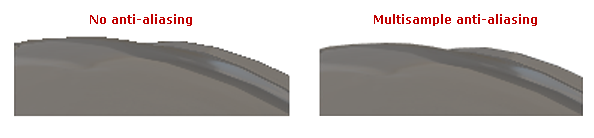
MultisamplingMode 属性可以设置为以下值:None、X2、X4、X8、X16、X32、X64。X2……X64 的值决定了每个像素用于计算最终颜色的采样点数量。采样点越多,效果越好,但计算成本也越高。
MultisamplingMode属性的默认值是X8。- 并非所有 MSAA 模式都受您的 GPU 支持。如果选择了不受支持的 MSAA 模式,系统会回退到较低的可用模式。您可以使用
Graphics3DControl.AvailableMultisamplingModes属性来返回您的显卡驱动程序所支持的 MSAA 模式列表。 - 对于较大的 3D 模型,多重采样会增加内存占用和计算成本。为了在这种情况下提高应用程序性能,请考虑将
MultisamplingMode设置为较低的值,或禁用 MSAA。
材质
Graphics3DControl 控件中的每个网格都可以使用自己的材质进行绘制。材质指定了表面与光线的交互方式,从而赋予对象其视觉外观。
Graphics3DControl 控件支持两种材质类型:
-
SimplePbrMaterial— 一种使用数值(例如颜色,如基础色和自发光,以及光交互设置,如金属度和粗糙度)来定义表面视觉属性的材质。有关更多信息,请参阅简单材质(SimplePbrMaterial) -
TexturedPbrMaterial— 一种 PBR 格式的纹理材质。此材质使用纹理(位图)来指定表面的视觉属性。有关更多信息,请参阅纹理材质(TexturedPbrMaterial)
要将材质应用于网格,请执行以下操作:
- 创建并初始化材质。
- 将材质的
Key属性设置为唯一字符串。这些键用于在将材质分配给网格时进行材质识别。 - 将材质添加到
Graphics3DControl.Materials集合中。 - 使用
MeshGeometry3D.MaterialKey属性将网格与特定材质关联起来。为此,将MeshGeometry3D.MaterialKey属性设置为目标材质的Key属性值。
示例 - 将材质分配给网格
以下示例创建了三种材质(SimplePbrMaterial 对象),并将其中一种材质应用于某个网格。所创建的材质通过唯一的字符串键(“BrownColor”、“TomatoColor” 和 “VioletColor”)进行标识。
using DynamicData;

g3DControl.Materials.AddRange(
    new[] {
        new SimplePbrMaterial(Color.FromUInt32(0xFF822c2e), "BrownColor"),
        new SimplePbrMaterial(Color.FromUInt32(0xffeb523f), "TomatoColor"),
        new SimplePbrMaterial(Color.FromUInt32(0xFFea3699), "VioletColor")
    }
);

//...

mesh1.MaterialKey = "VioletColor";
简单材质(SimplePbrMaterial)
SimplePbrMaterial 是一种以数值形式描述表面视觉属性的材质。它提供以下成员用于指定视觉设置:
-
Albedo— 基础颜色。该属性的值是一个 Vector3 对象,其 X、Y、Z 成员分别指定红、绿、蓝三个颜色分量的归一化值。归一化值的范围是 [0;1]。要将标准颜色分量(0–255)转换为归一化值,请将其除以 255。您也可以使用
SimplePbrMaterial构造函数,从指定的Color对象初始化Albedo和Alpha属性。此构造函数会自动对颜色分量进行归一化。 -
Alpha— 透明度级别。该属性的值应在 [0;1] 范围内,其中
0表示完全透明,1表示完全不透明。 -
Emission— 表面发光的强度。该属性的值是一个 Vector3 对象,其 X、Y、Z 成员分别指定红、绿、蓝三个颜色分量的归一化值。归一化值的范围是 [0;1]。要将标准颜色分量(0–255)转换为归一化值,请将其除以 255。
-
AmbientOcclusion— 由阻挡环境光的对象所造成的阴影级别。该属性的值应在 [0;1] 范围内,其中
0表示应用最大程度的环境光遮蔽效果,1表示不应用环境光遮蔽。 -
Roughness— 表面的光滑程度。该属性的值应在 [0;1] 范围内,其中
0表示完全光滑有光泽的表面,1表示完全粗糙、无光泽的表面。 -
Metallic— 表面的反射率。该属性的值应在 [0;1] 范围内,其中
0表示非金属表面,1表示完全金属材质。
演示
演示应用程序中的 Simple Materials 示例展示了使用简单材质绘制的 3D 模型。该演示允许您实时调整材质的设置,并即时查看更改效果。
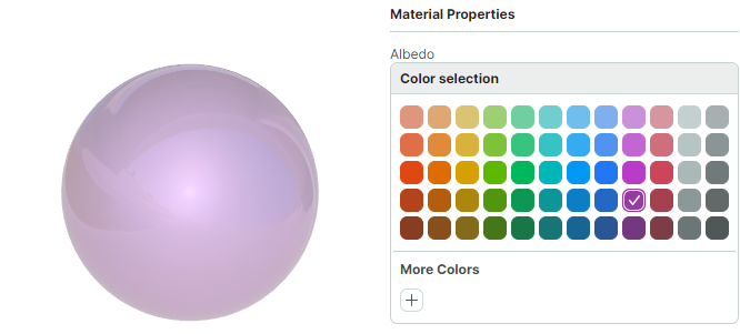
示例 - 将简单材质应用于模型
以下代码创建了一个简单材质(SimplePbrMaterial 对象),并将其应用于某个 3D 模型的第一个网格。
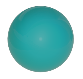
SimplePbrMaterial.Albedo 属性使用归一化颜色坐标被设置为基础颜色(Teal,蓝绿色)。
SimplePbrMaterial material = new SimplePbrMaterial();
material.Albedo = ToNormalizedVector3(Colors.Teal);
material.Emission = ToNormalizedVector3(Colors.Black);
material.Metallic = 0;
material.Roughness = 0.5f;
material.AmbientOcclusion = 1;
material.Key = "myFavMaterial";
g3DControl.Materials.Add(material);

// Apply the material to the first mesh of the model
g3DControl.Models[0].Meshes[0].MaterialKey = "myFavMaterial";


public static Vector3 ToNormalizedVector3(Color color)
{
    return new Vector3(color.R/255f, color.G/255f, color.B/255f);
}
将该材质应用于一个示例 3D 模型的效果如下所示:
纹理材质(TexturedPbrMaterial)
TexturedPbrMaterial 是一种使用 PBR 纹理(位图)来定义表面视觉属性的材质。TexturedPbrMaterial 类提供以下成员用于配置材质的设置:
-
Albedo— 指定材质基础颜色的位图。 -
Alpha— 指定透明度级别的位图。 -
Emission— 指定表面发光强度的位图。 -
AmbientOcclusion— 指定由阻挡环境光的对象所造成阴影级别的位图。 -
Roughness— 指定表面光滑程度的位图。 -
Metallic— 指定表面反射率的位图。 -
Normal— 指定法线贴图(Normal Map)的位图。
演示
演示应用程序中的 Textured Materials 示例展示了使用 PBR 纹理渲染的 3D 模型。这些纹理从存储在应用程序资源中的图形文件加载而来。
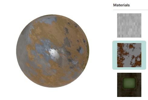
以下来自 Textured Materials 演示的代码片段,用材质(TexturedPbrMaterial 对象)填充了视图模型的 Materials 集合。这些材质是根据存储在应用程序资源中 DemoCenter.Resources.Graphics3D.Materials 文件夹下、以 ZIP 文件形式存放的所有纹理创建的。对于每个材质,如果包含纹理的 ZIP 文件中包含 Albedo、AmbientOcclusion、Metallic、Roughness、Normal 和 Emission 设置所需的位图,这些位图就会被加载并应用到该材质上。
public partial class Graphics3DControlTexturedMaterialsViewModel : Graphics3DControlViewModel
{
    [ObservableProperty] ObservableCollection<TexturedPbrMaterial> materials = new();
    [ObservableProperty] TexturedPbrMaterial selectedMaterial;

    public Graphics3DControlTexturedMaterialsViewModel()
    {
        var assembly = Assembly.GetAssembly(typeof(Graphics3DControlViewModel));
        var textureNames = assembly!.GetManifestResourceNames().Where(name => name.StartsWith("DemoCenter.Resources.Graphics3D.Materials."));
        foreach (var textureName in textureNames)
            materials.Add(LoadMaterial(assembly, textureName));
        selectedMaterial = Materials.First();
        //...
    }

    static TexturedPbrMaterial LoadMaterial(Assembly assembly, string resourceName)
    {
        var stream = assembly!.GetManifestResourceStream(resourceName);
        using var archive = new ZipArchive(stream!, ZipArchiveMode.Read);
        var material = new TexturedPbrMaterial { Key = resourceName.Split('.')[^2] };
        foreach (var entry in archive.Entries)
        {
            using var entryStream = entry.Open();
            using var memoryStream = new MemoryStream();
            entryStream.CopyTo(memoryStream);
            memoryStream.Seek(0, SeekOrigin.Begin);
            var bitmap = new Bitmap(memoryStream);
            if (entry.Name.StartsWith("Albedo"))
                material.Albedo = bitmap;
            else if (entry.Name.StartsWith("AO"))
                material.AmbientOcclusion = bitmap;
            else if (entry.Name.StartsWith("Metallic"))
                material.Metallic = bitmap;
            else if (entry.Name.StartsWith("Roughness"))
                material.Roughness = bitmap;
            else if (entry.Name.StartsWith("Normal"))
                material.Normal = bitmap;
            else if (entry.Name.StartsWith("Emissive"))
                material.Emission = bitmap;
        }
        return material;
    }
}
以下来自 Textured Materials 演示的 XAML 代码,将 Graphics3DControl 控件绑定到视图模型中的材质集合(Graphics3DControlTexturedMaterialsViewModel.Materials)。当前应用的材质由 Graphics3DControlTexturedMaterialsViewModel.SelectedMaterial 属性指定。
<mx3d:Graphics3DControl x:Name="DemoControl" MaterialsSource="{Binding Materials}">
    <mx3d:GeometryModel3D>
        <mx3d:MeshGeometry3D Vertices="{Binding Vertices}" Indices="{Binding Indices}" MaterialKey="{Binding SelectedMaterial.Key}" />
    </mx3d:GeometryModel3D>
</mx3d:Graphics3DControl>
纹理坐标
使用纹理材质时,您需要将纹理映射到某个表面。为此,请初始化网格中顶点的 Vertex3D.TextureCoord 属性。此属性指定纹理坐标(通常称为 UV 坐标)。
纹理坐标是顶点所映射到的二维坐标 (x, y)。
-
x表示纹理中的水平坐标,范围为 [0; 1],其中0表示图像的左边缘,1表示图像的右边缘。 -
y表示纹理中的垂直坐标,范围为 [0; 1],其中0表示图像的上边缘,1表示图像的下边缘。
例如,坐标 (x, y) 为 (0.5, 0.5) 将采样纹理中心的像素。
示例
演示 Vertex3D.TextureCoord 属性用法的示例:
-
Textured Materials演示。 -
本文档中定义点网格一节中的示例。
背面剔除和正面剔除
Graphics3DControl.CullMode 属性允许您为三角形网格启用背面剔除和正面剔除。剔除模式决定了 3D 模型的哪些面应被绘制,哪些应被丢弃。您可以将 Graphics3DControl.CullMode 属性设置为以下值:
-
CullMode.Back— 启用背面剔除,即不绘制三角形的背面。 -
CullMode.Front— 启用正面剔除,即不绘制三角形的正面。 -
CullMode.None— 正面和背面都会被绘制。
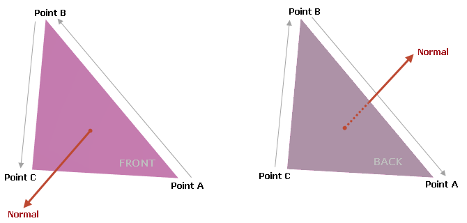
识别面的正面和背面
当您为网格定义三角形面时,使用 MeshGeometry3D.Indices 属性来指定构成每个三角形的顶点索引。
每个网格三角形的索引顺序很重要,因为它决定了表面法线的方向,从而决定了三角形的正面和背面:
-
如果三角形的索引按逆时针方向排列,表面法线指向观察者,此时观察者看到的是该三角形的正面。
-
如果三角形的索引按顺时针方向排列,表面法线指向远离观察者的方向,此时观察者看到的是该三角形的背面。
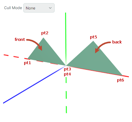
示例
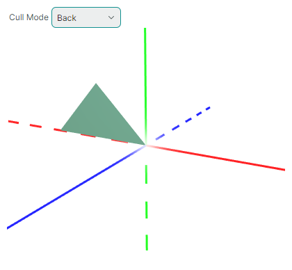
本示例演示了面剔除功能。 在此示例中,创建了一个由两个三角形组成的模型。显示时,观察者看到的是第一个(左侧)三角形的正面和第二个(右侧)三角形的背面。
xmlns:mx3d="https://schemas.eremexcontrols.net/avalonia/controls3d"

<mx3d:Graphics3DControl Name="g3DControl" ShowAxes="True"/>
using Avalonia.Media;
using DynamicData;

GeometryModel3D model = new GeometryModel3D();
g3DControl.Models.Add(model);

Vector3 pt1 = new(-1f, 0, 0);
Vector3 pt2 = new(-0.5f, 0.5f, 0);
Vector3 pt3 = new(0, 0, 0);
Vector3 pt4 = new(0, 0, 0);
Vector3 pt5 = new(0.5f, 0.5f, 0);
Vector3 pt6 = new(1f, 0, 0);

MeshGeometry3D mesh1 = new MeshGeometry3D();
mesh1.FillType = MeshFillType.Triangles;
Vertex3D[] meshVertices = new Vertex3D[]
{
    new Vertex3D() { Position = pt1,  Normal = new Vector3(0, 0, 1) },
    new Vertex3D() { Position = pt2,  Normal = new Vector3(0, 0, 1) },
    new Vertex3D() { Position = pt3,  Normal = new Vector3(0, 0, 1) },
    new Vertex3D() { Position = pt4,  Normal = new Vector3(0, 0, -1) },
    new Vertex3D() { Position = pt5,  Normal = new Vector3(0, 0, -1) },
    new Vertex3D() { Position = pt6,  Normal = new Vector3(0, 0, -1) }
};
mesh1.Vertices = meshVertices;
// Vertices of the first triangle are enumerated counter-clockwise (pt3->pt2->pt1),
// while vertices of the second triangle are enumerated clockwise (pt4->pt5->pt6):
uint[] meshIndices = new uint[] { 2, 1, 0, 3, 4, 5 };
mesh1.Indices = meshIndices;
model.Meshes.AddRange(new MeshGeometry3D[] { mesh1 });
g3DControl.Materials.Add(new SimplePbrMaterial(Colors.SeaGreen, "myMaterial"));
mesh1.MaterialKey = "myMaterial";
当您将 Graphics3DControl.CullMode 属性设置为 CullMode.Back 时,背面不会被绘制。第二个(右侧)三角形背对摄像机,因此不会被绘制。
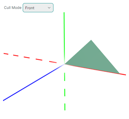
当 Graphics3DControl.CullMode 等于 CullMode.Front 时,正面不会被绘制。第一个(左侧)三角形面向摄像机,因此被隐藏:
伽马校正和曝光校正
Graphics3DControl.Exposure— 控制曝光校正级别,用于调整渲染图像的亮度。默认值为 4.5。该属性可以设置为非负值。Graphics3DControl.Gamma— 控制伽马校正。默认值为 2.2,这是大多数显示器的标准伽马值。该属性可以设置为非负值。
* 本页面使用机器翻译技术翻译。